Maintenance—455/A2/B2
individual items, but if the connectors are faulty, the entire
cable should be replaced.
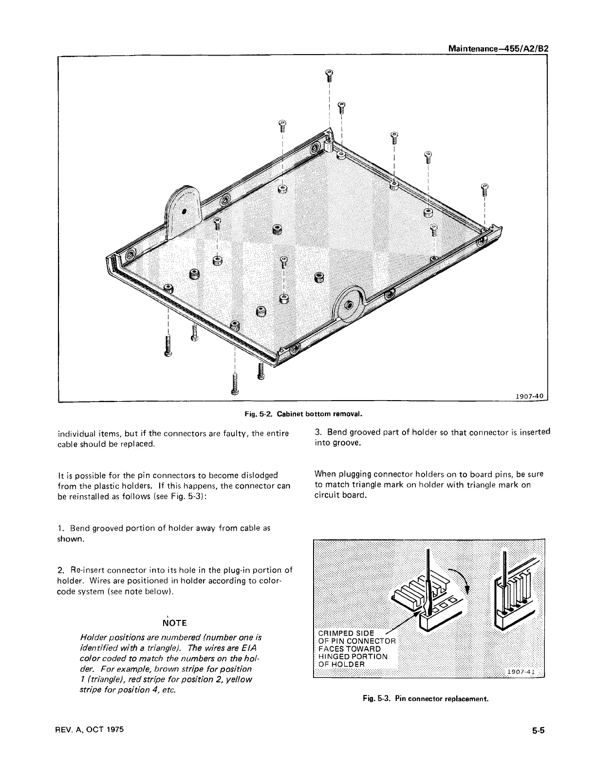
It is possible for the pin connectors to become dislodged
from the plastic holders. If this happens, the connector can
be reinstalled as follows (see Fig. 5-3):
1. Bend grooved portion of holder away from cable as
shown.
2. Re-insert connector into its hole in the plug-in portion of
holder. Wires are positioned in holder according to color-
code system (see note below).
NO T E
Holder positions are numbered (number one is
identified with a triangle). The wires are EIA
color coded to match the numbers on the hol
der. For example, brown stripe for position
1 (triangle), red stripe for position 2, yellow
stripe for position 4, etc.
3. Bend grooved part of holder so that connector is inserted
into groove.
When plugging connector holders on to board pins, be sure
to match triangle mark on holder with triangle mark on
circuit board.
REV. A, OCT 1975
5-5
Fig. 5-3. Pin connector replacement.

 Loading...


