Operating Instructions—455/A2/B2
2. Set the VERT MODE switch to either CHOP or ALT.
In general, CHOP is more suitable for low-frequency
signals and the ALT position is more suitable for high-
frequency signals. Position both traces to the graticule
horizontal centerline.
3. Set the triggering SOURCE switch to CH 1.
4. Connect the reference signal to the CH 1 input connector
and the comparison signal to the CH 2 input connector. Use
coaxial cables or probes which have equal time delay to
connect the signals to the input connectors.
5. If the signals are of opposite polarity, set the INVERT
switch in to invert the Channel 2 display. (Signals may be
of opposite polarity due to 180° phase difference; if so,
take this into account in the final calculation.)
6. Set the CH 1 and CH 2 VOLTS/DIV switches and the
CH 1 and CH 2 VAR controls so the displays are equal and
about five divisions in amplitude.
7. Set the TIM E/DIV switch to a sweep rate which displays
about one cycle of the reference waveform.
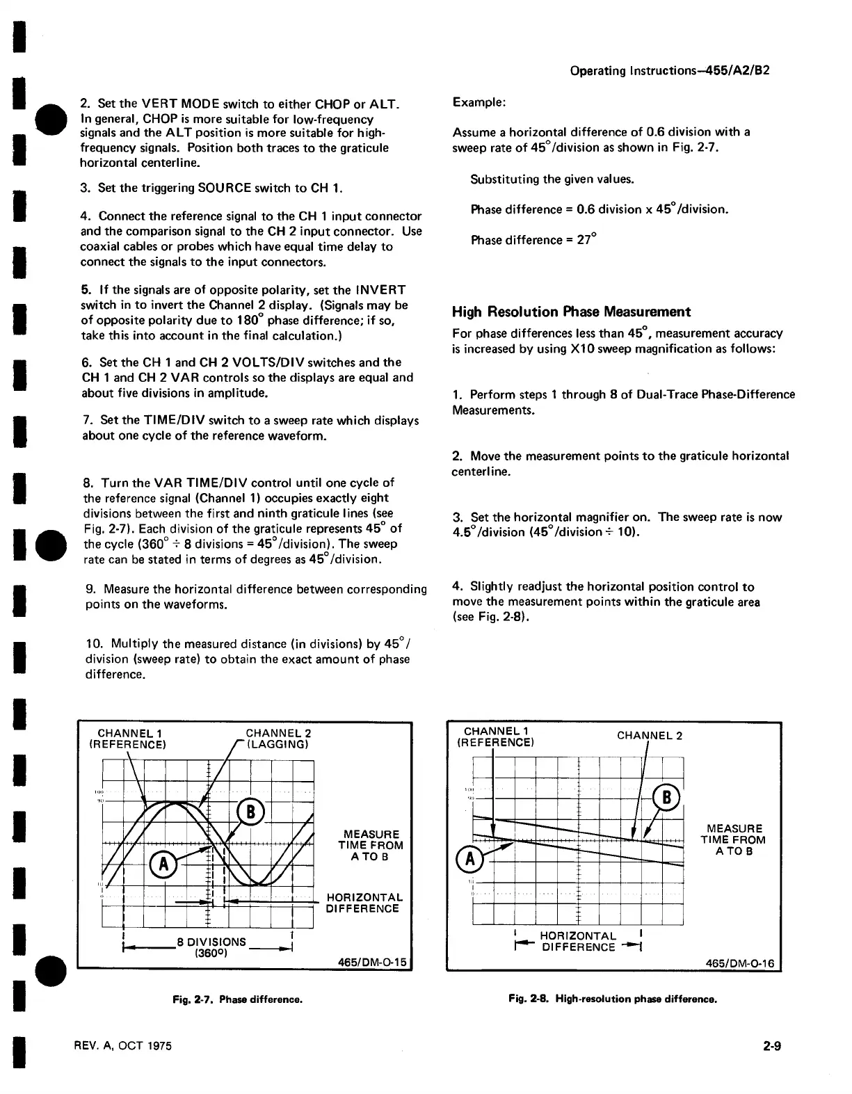
8. Turn the VAR TIME/DIV control until one cycle of
the reference signal (Channel 1) occupies exactly eight
divisions between the first and ninth graticule lines (see
Fig. 2-7). Each division of the graticule represents 45° of
the cycle (360° -r 8 divisions = 45°/division). The sweep
rate can be stated in terms of degrees as 45°/division.
9. Measure the horizontal difference between corresponding
points on the waveforms.
10. Multiply the measured distance (in divisions) by 45°/
division (sweep rate) to obtain the exact amount of phase
difference.
Example:
Assume a horizontal difference of 0.6 division with a
sweep rate of 45°/division as shown in Fig. 2-7.
Substituting the given values.
Phase difference = 0.6 division x 45°/division.
Phase difference = 27°
High Resolution Phase Measurement
For phase differences less than 45°, measurement accuracy
is increased by using X I0 sweep magnification as follows:
1. Perform steps 1 through 8 of Dual-Trace Phase-Difference
Measurements.
2. Move the measurement points to the graticule horizontal
centerline.
3. Set the horizontal magnifier on. The sweep rate is now
4.5°/division (45°/division -f- 10).
4. Slightly readjust the horizontal position control to
move the measurement points within the graticule area
(see Fig. 2-8).
CHANNEL 1 CHANNEL 2
MEASURE
TIM E FROM
A TO B
HORIZONTAL
DIFFERENCE
465/D M -0-15
REV. A, OCT 1975
2-9
Fig. 2-7. Phase difference.
Fig. 2-8. High-resolution phase difference.

 Loading...


