Maintenance—455/A2/B2
A and B Timing Switch Board Removal
To remove switch assembly:
1. Set A and B TIME/DIV knobs to .2 ps.
2. Remove VAR and A and B TIME/DIV knobs using
hex wrench.
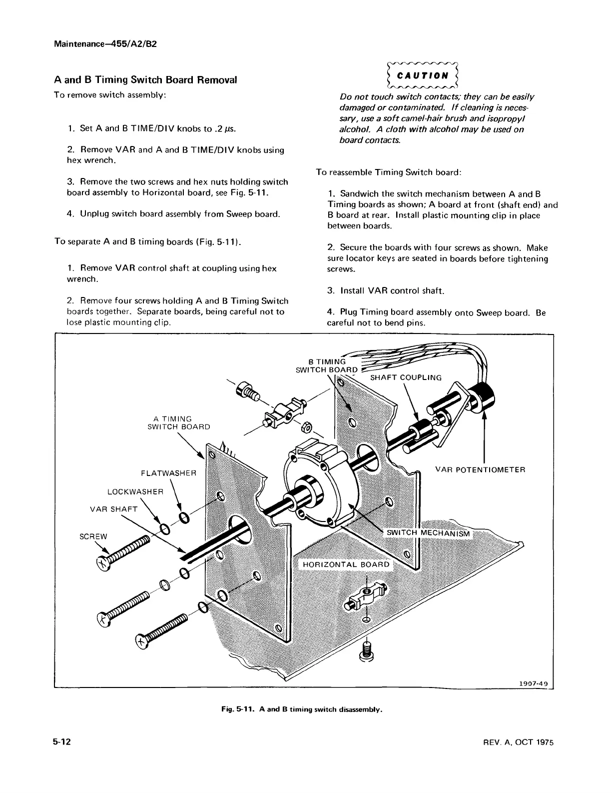
3. Remove the two screws and hex nuts holding switch
board assembly to Horizontal board, see Fig. 5-11.
4. Unplug switch board assembly from Sweep board.
Do n ot touch switch contacts; they can be easily
damaged or contaminated. I f cleaning is neces
sary, use a soft camel-hair brush and isopropyl
alcohol. A d oth w ith alcohol may be used on
board contacts.
To reassemble Timing Switch board:
1. Sandwich the switch mechanism between A and B
Timing boards as shown; A board at front (shaft end) and
B board at rear. Install plastic mounting clip in place
between boards.
To separate A and B timing boards (Fig. 5-11).
1. Remove VAR control shaft at coupling using hex
wrench.
2. Remove four screws holding A and B Timing Switch
boards together. Separate boards, being careful not to
lose plastic mounting clip.
2. Secure the boards with four screws as shown. Make
sure locator keys are seated in boards before tightening
screws.
3. Install VAR control shaft.
4. Plug Timing board assembly onto Sweep board. Be
careful not to bend pins.
Fig. 5-11. A and B timing switch disassembly.
5-12
REV. A, OCT 1975