Performance Check—455/A2/B 2
j. CHECK—Display is triggered along negative-going
slope of waveform as B LEVEL control is rotated and is
not triggered (not visible) at either extreme of B LEVEL
rotation.
NOTE
I f the 11th time marker is n ot visible, set the A
TIM E/DIV switch one position counterclock
wise from the B TIM E/DIV switch. Example:
k. Disconnect test equipment.
A TIM E/DIV 1ms
B TIM E/DIV 0.5ms
21. A AND B SWEEP RATE ACCURACY
a. Set: A SOURCE NORM
B SOURCE STARTS AFTER
DELAY
A and B SLOPE OUT: +
HORIZ DISPLAY A
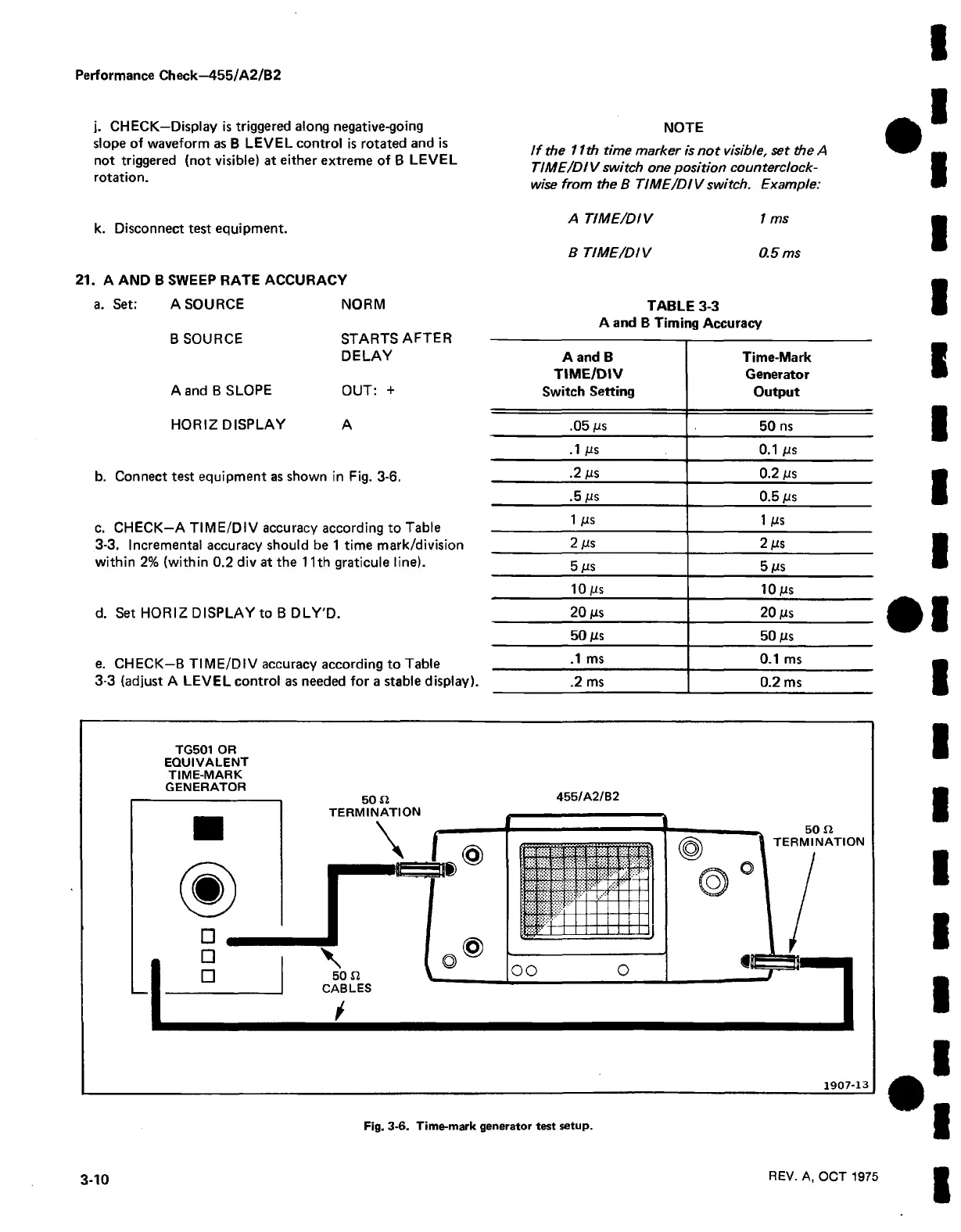
b. Connect test equipment as shown in Fig. 3-6.
c. CHECK—A TIME/DIV accuracy according to Table
3-3. Incremental accuracy should be 1 time mark/division
within 2% (within 0.2 div at the 11th graticule line).
d. Set HORIZ DISPLAY to B DLY'D.
e. CHECK—B TIM E/DIV accuracy according to Table
3-3 (adjust A LEVEL control as needed for a stable display).
TABLE 3-3
A and B Timing Accuracy
A and B
Time-Mark
TIME/DIV
Generator
Switch Setting
Output
.05 jus
50 ns
.1 ps
0.1 jus
.2 jus 0.2 jus
.5 jus
0.5 jus
1 jus
1 JUS
2 jus
2 jus
5 jus
5 jus
10 jus
10 jus
20 jus
20 jus
50 jus
50 jus
.1 ms 0.1 ms
.2 ms
0.2 ms
TG501 OR
EQUIVALENT
TIME-MARK
1907-13
Fig. 3-6. Time-mark generator test setup.
3-10
REV. A, OCT 1975

 Loading...


