Performance Check—455/A2/B2
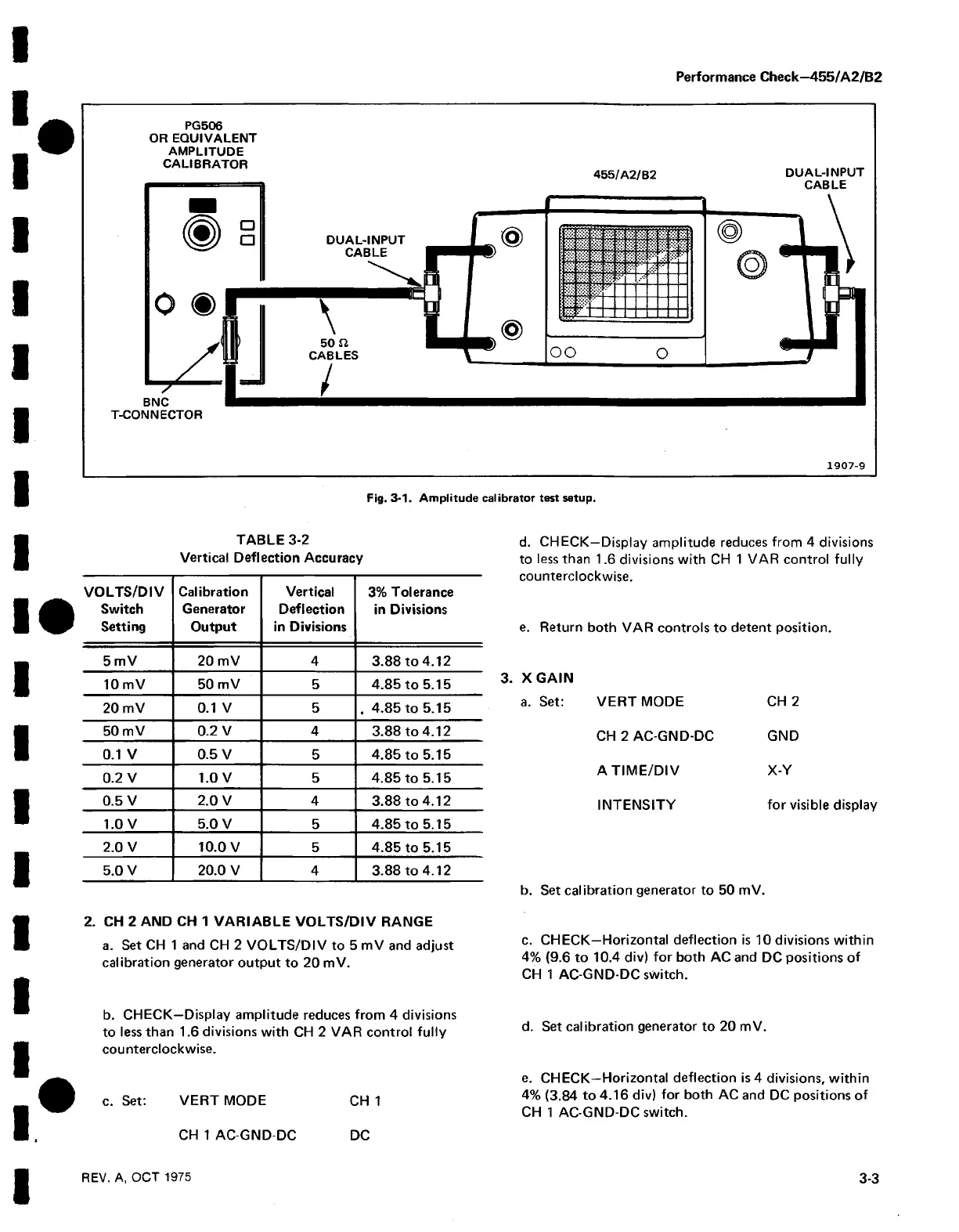
PG506
OR EQ UIVALENT
AM PLITUDE
CALIBRATOR
a
a
o ®
7
BNC
T-CONNECTOR
455/A 2/B2
DUAL-INPUT
CABLE
DUAL-INPUT
CABLE
\
50 n
CABLES
/
f t I t I
1
iSreW
1 1 1 1
oo o
1907-9
Fig. 3-1. Amplitude calibrator test setup.
TABLE 3-2
Vertical Deflection Accuracy
VOLTS/DIV
Switch
Setting
Calibration
Generator
Output
Vertical
Deflection
in Divisions
3% Tolerance
in Divisions
5 mV
20 mV 4 3.88 to 4.12
10 mV
50 mV
5 4.85 to 5.15
20 mV
0.1 V 5 , 4.85 to 5.15
50 mV
0.2 V
4 3.88 to 4.12
0.1 V 0.5 V
5 4.85 to 5.15
0.2 V
1.0 V 5 4.85 to 5.15
0.5 V 2.0 V 4 3.88 to 4.12
1.0 V 5.0 V 5 4.85 to 5.15
2.0 V 10.0 V 5
4.85 to 5.15
5.0 V 20.0 V 4 3.88 to 4.12
2. CH 2 AND CH 1 VARIABLE VOLTS/DIV RANGE
a. Set CH 1 and CH 2 VOLTS/DIV to 5 mV and adjust
calibration generator output to 20 mV.
d. CHECK—Display amplitude reduces from 4 divisions
to less than 1.6 divisions with CH 1 VAR control fully
counterclockwise.
e. Return both VAR controls to detent position.
3. X GAIN
a. Set: VERTMODE CH 2
CH 2 AC-GND-DC GND
A TIM E/DIV X-V
INTENSITY for visible display
b. Set calibration generator to 50 mV.
c. CHECK—Horizontal deflection is 10 divisions within
4% {9.6 to 10.4 div) for both AC and DC positions of
CH 1 AC-GND-DC switch.
b. CHECK—Display amplitude reduces from 4 divisions
to less than 1.6 divisions with CH 2 VAR control fully
counterclockwise.
c. Set: VERT MODE CH 1
d. Set calibration generator to 20 mV.
e. CHECK—Horizontal deflection is 4 divisions, within
4% (3.84 to 4.16 div) for both AC and DC positions of
CH 1 AC-GND-DC switch.
CH 1 AC-GND-DC DC
REV. A, OCT 1975
3-3

 Loading...


