To use.
■
Click the Trigger Type box and select Bus from the drop-down list.
■
Click the Bus box and select the bus number or name from the drop-down list.
NOTE. You have the option to add a user-defined label for bus sources.
■
Click the Logic Thresholds Setup button to set the voltage threshold levels for the channels in the bus.
■
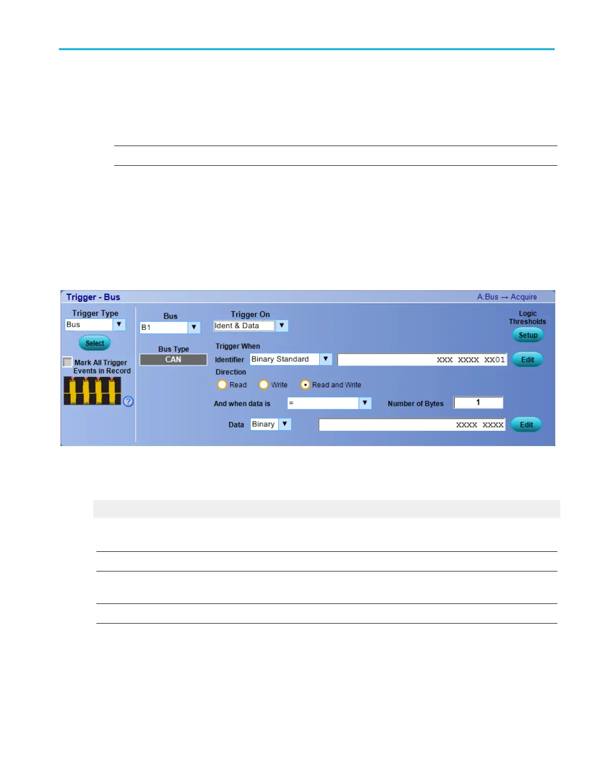
Select the type of bus cycle or activity to use as the trigger from the Trigger On drop-down list.
■
For some Trigger On selections, you must set additional fields to define other parameters such as for a Ident & Data.
In this example, you need to set the Trigger When Identifier, When Direction values, and select the And when data is
values. You can also set the component threshold levels through the Logic Thresholds Setup button.
Select the Trigger On selections to view their parameters.
What do you want to do next?
Learn about bus setups.
Set up a CAN bus trigger
NOTE. The CAN Bus Trigger type is only available on DPO7000C Series instruments.
From the Trig menu, select CAN Setup.
NOTE. You must install Low Speed Serial Analysis (CAN/LIN trigger) before you can access the CAN triggers.
Overview. Use the controls in this window to set up the parameters to trigger on a CAN bus.
Trigger setups
DPO70000SX, MSO/DPO70000DX, MSO/DPO70000C, DPO7000C, and MSO/DPO5000B Series 399
 Loading...


