Runt trigger
A runt trigger occurs when the instrument detects a short pulse that crosses one threshold but fails to cross a second threshold
before recrossing the first.
■
You can set the instrument to detect any positive or negative runt pulse, or only those wider than a specified minimum width.
■
Runt pulses can also be qualified by the logical state of other channels.
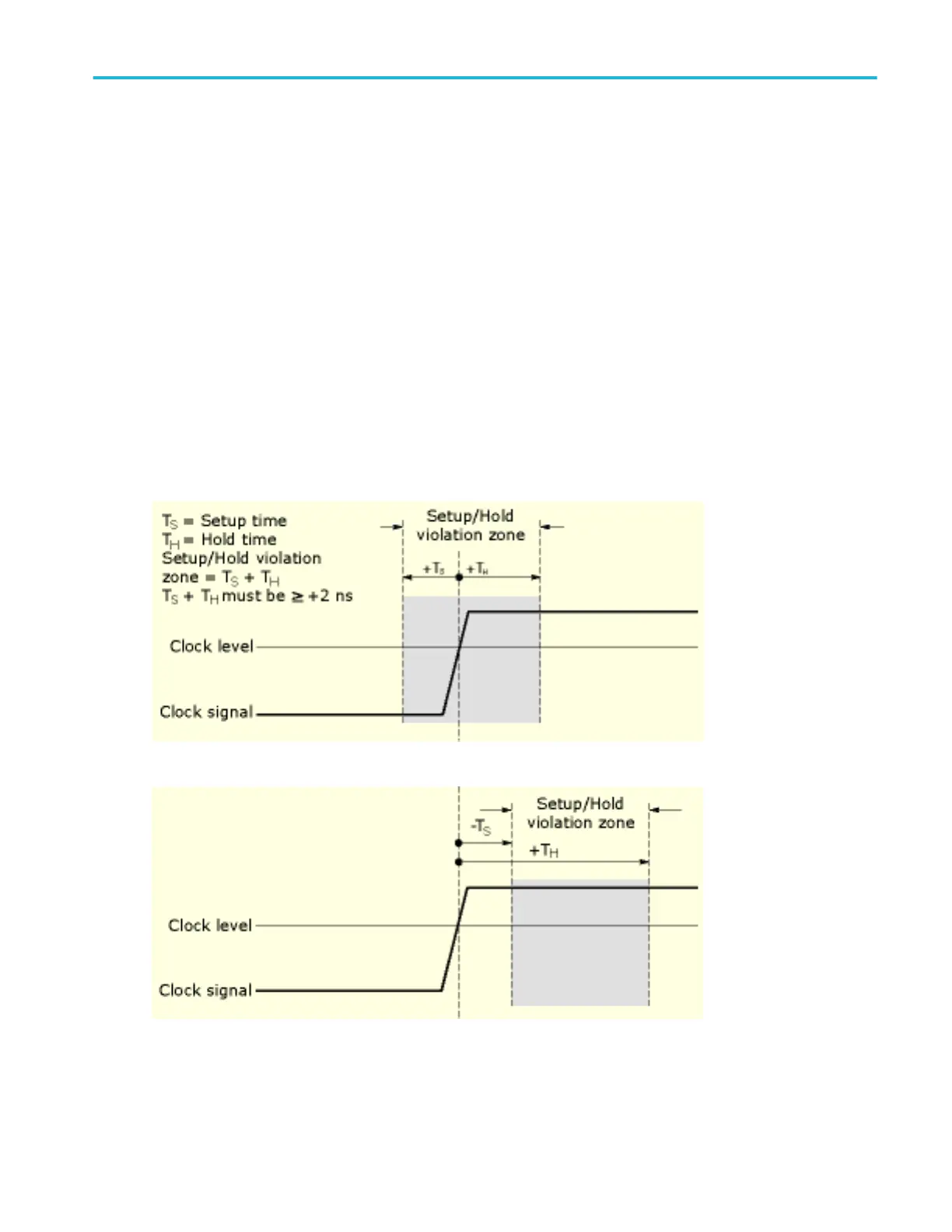
Setup and hold trigger
A setup/hold trigger occurs when a data signal changes state inside of the user specified setup and hold times relative to the
clock. When you use setup/hold triggering, you define:
■
The channel containing the logic input (the data source) and the channel containing the clock (the clock source)
■
The direction of the clock edge to use
■
The clocking level and data level that the instrument uses to determine if a clock or data transition has occurred
■
The setup and hold times that together define a time range relative to the clock
Data that changes state within the setup/hold violation zone triggers the instrument. The next figure shows how the setup and
hold times that you choose position the violation zone relative to the clock.
Oscilloscope reference
DPO70000SX, MSO/DPO70000DX, MSO/DPO70000C, DPO7000C, and MSO/DPO5000B Series 671