Chapter 1 Overview
2 CNT-SVN01C-EN
Additional components
The Tracer MP581 controller requires additional components for certain
applications and has several options for adding an operator display.
Operator display models
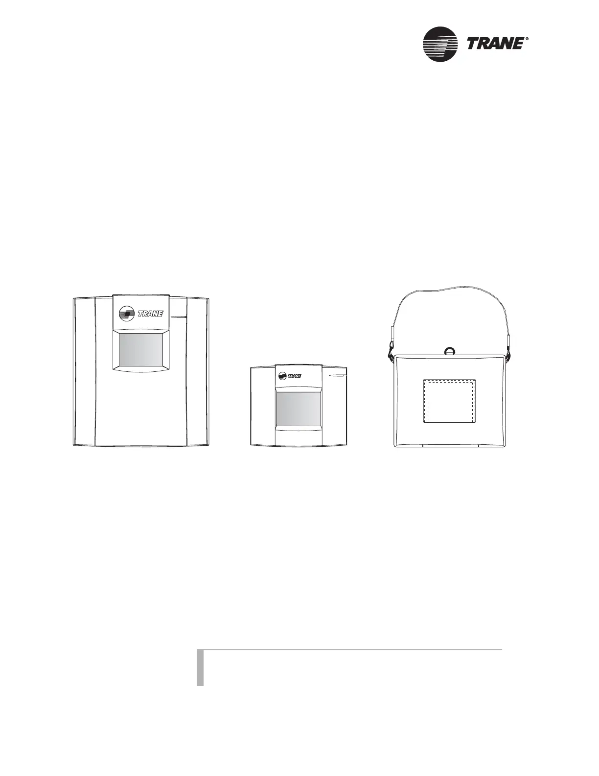
The operator display is available in three models (see Figure 1):
• Door-mounted operator display
• Stand-alone operator display, for mounting up to 150 ft (46 m) from
the controller
• Portable operator display with carrying case
Figure 1. Operator display models
Sensors
The Tracer MP581 supports the following sensors:
• Zone temperature sensors (thermistors and linear resistance for
thumbwheels)
• Linear 0–20 mA, such as humidity sensors
• Pressure sensors (use only the Trane 5 Vdc pressure-sensor kit—part
number 4020 1159)
• Linear 0–10 Vdc, such as indoor air-quality sensors
• Resistance temperature detectors (up to four)
• Motion sensors, time clocks, and other binary switch devices
The Rover service tool is required to configure Tracer MP581 inputs for
all types of sensors.
Door-mounted
operator display
Stand-alone
operator display
Portable
operator display
Note:
The Tracer MP581 supports all Trane zone sensors but does not
support fan switches (HIGH, MED, LOW, AUTO, and OFF).

 Loading...


