Chapter 5 Wiring inputs and outputs
26 CNT-SVN01C-EN
Wiring binary outputs
The Tracer MP581 controller has six binary outputs. These are powered
outputs, not dry-contact outputs.
IMPORTANT
Use pilot relays for dry-contact outputs and when the load current is
greater than 0.5 A. Use powered outputs when the load current is less
than 0.5 A.
To wire a binary output:
1. Connect the common wire to a common terminal as shown in
Figure 17.
2. Connect the shield wire to a common terminal at the termination
board and tape it back at the output device.
3. Connect the signal wire to an available binary output terminal
(BO1–BO6).
4. Use the Rover service tool to configure the binary output.
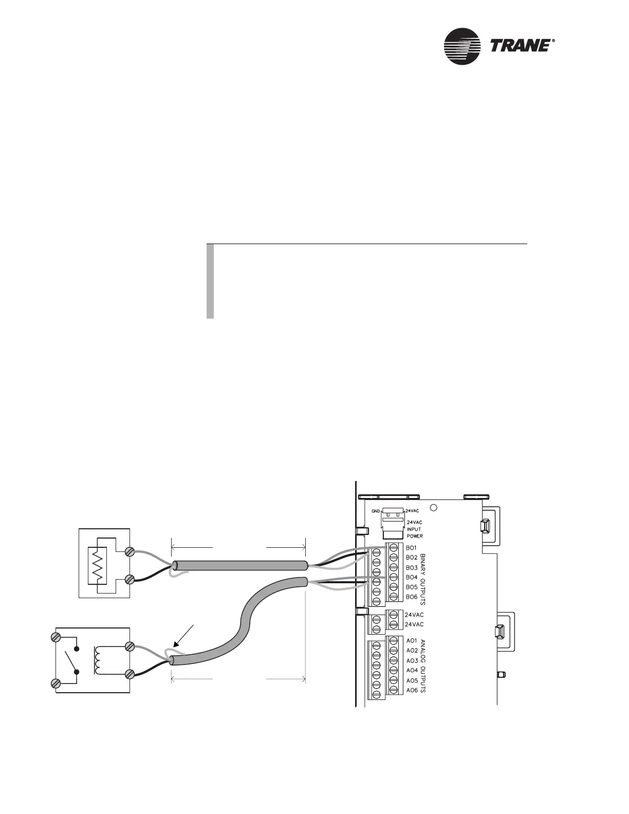
Figure 17. Wiring binary outputs
Note:
When controlling coil-based loads, such as pilot relays, do not
forget to account for “inrush” current. Inrush current can be
three (or more) times greater than the operating current. You
can find information on inrush current for specific types of out-
puts in their product specifications.
Powered output
< 1000 ft
(300 m)
< 1000 ft
(300 m)
Pilot relay
24 Vac coil
Signal
Common
Signal
Common
Tape back shield

 Loading...


