Chapter 7 Wiring Comm5 links
48 CNT-SVN01C-EN
Wiring Comm5 to the Tracer MP581
IMPORTANT
When installing the Tracer MP581 controller in areas of high electro-
magnetic interference (EMI) and radio frequency interference (RFI), fol-
low the additional installation instructions in “EMI/RFI considerations”
on page 50.
To wire the Comm5 link:
1. At the first Tracer MP581 on the link, complete the following steps:
• Connect the shield wire to a ground, either at a common terminal
on the termination board or on the main circuit board (see
Figure 28 and Figure 29 on page 49).
If you choose to ground the shield wire to the main board, use a
#6 (3.5 mm) screw (not supplied) to secure the shield wire.
• Connect the white wire to the first (or third) Comm5 screw termi-
nal as shown in Figure 28.
• Connect the black wire to the second (or fourth) Comm5 screw
terminal.
• If this is the first Comm5 controller on the daisy chain, place a
100 Ω termination resistor across the Comm5 screw terminals.
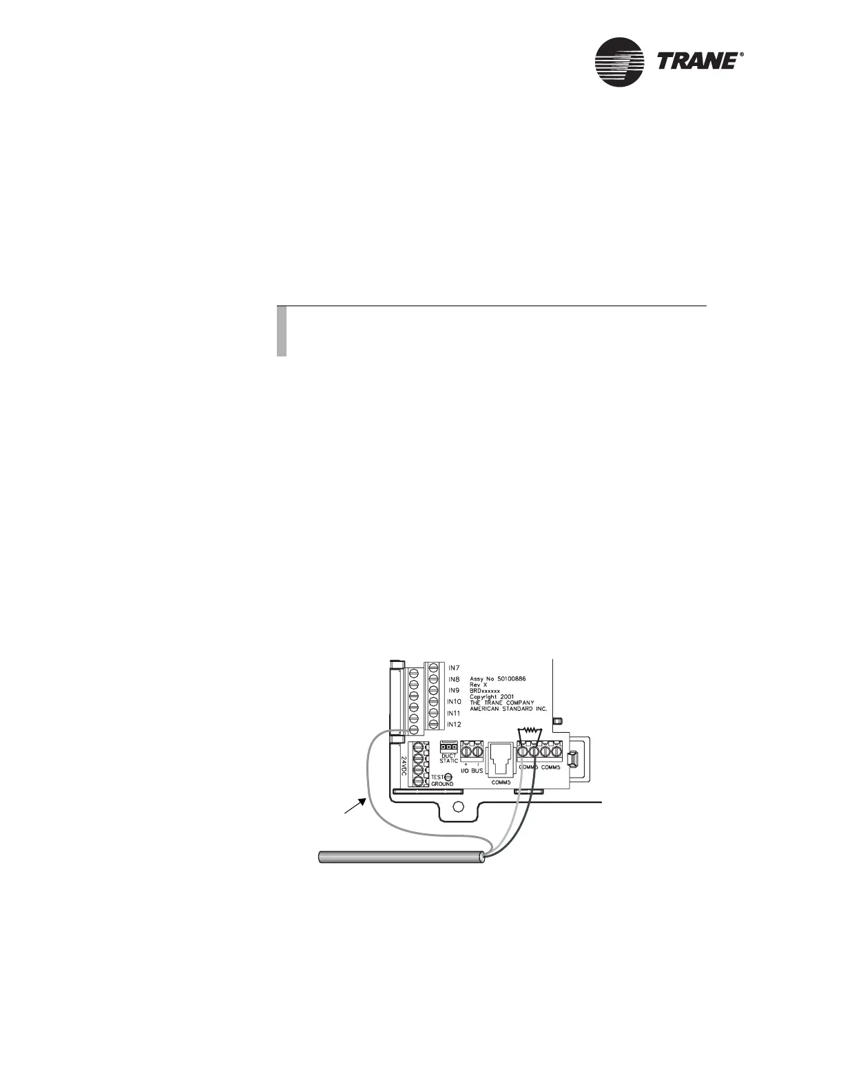
Figure 28. Grounding on the termination board
Note:
Although Comm5 links are not polarity sensitive, we recom-
mend that you keep polarity consistent throughout the site.
Shield wire
Note: Place a 100 Ω termination
resistor at the first and last Comm5
device on the daisy chain.

 Loading...


