Chapter 5 Wiring inputs and outputs
18 CNT-SVN01C-EN
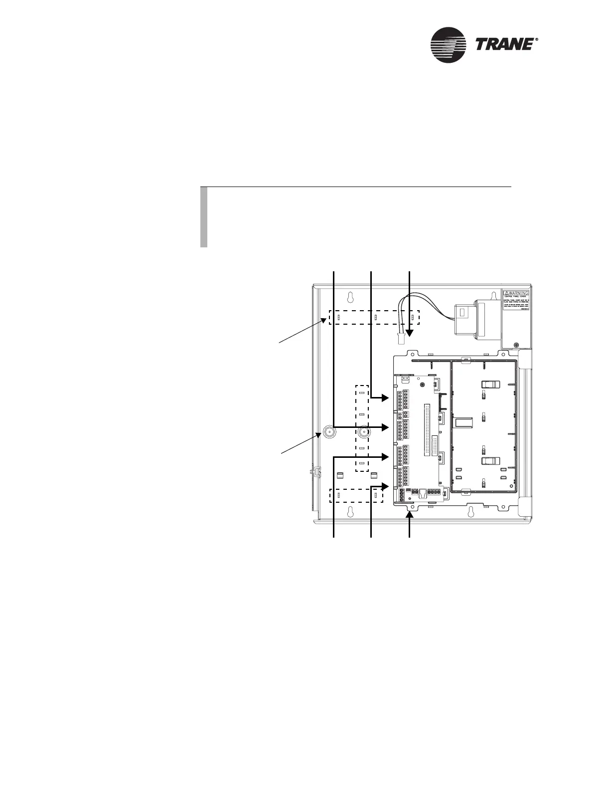
Wire routing
Figure 10 shows how to route input/output wires through the enclosure.
It also shows the locations of wire-tie brackets. See Figure 6 on page 11
for knockout locations and dimensions. Metal conduit may be required by
local codes when running input/output wires.
Figure 10. Wire routing
Note:
If your application requires a pressure sensor, install the pres-
sure sensor before wiring other inputs and outputs. (So that the
mounting holes are not covered by wires.) For more informa-
tion, refer to Chapter 6, “Installing the pressure sensor.”
Brackets for wire
ties (9 locations)
Mounting holes for
pressure sensor
(sensor will affect
wire routing)
Recommended
communication wire route

 Loading...


