Chapter 2 Installing the frame-mounted Tracer MP581
8 CNT-SVN01C-EN
Installing the termination board
To install the termination board in a separately purchased enclosure or in
other equipment:
1. Remove the controller from its packaging and separate the top and
bottom frames.
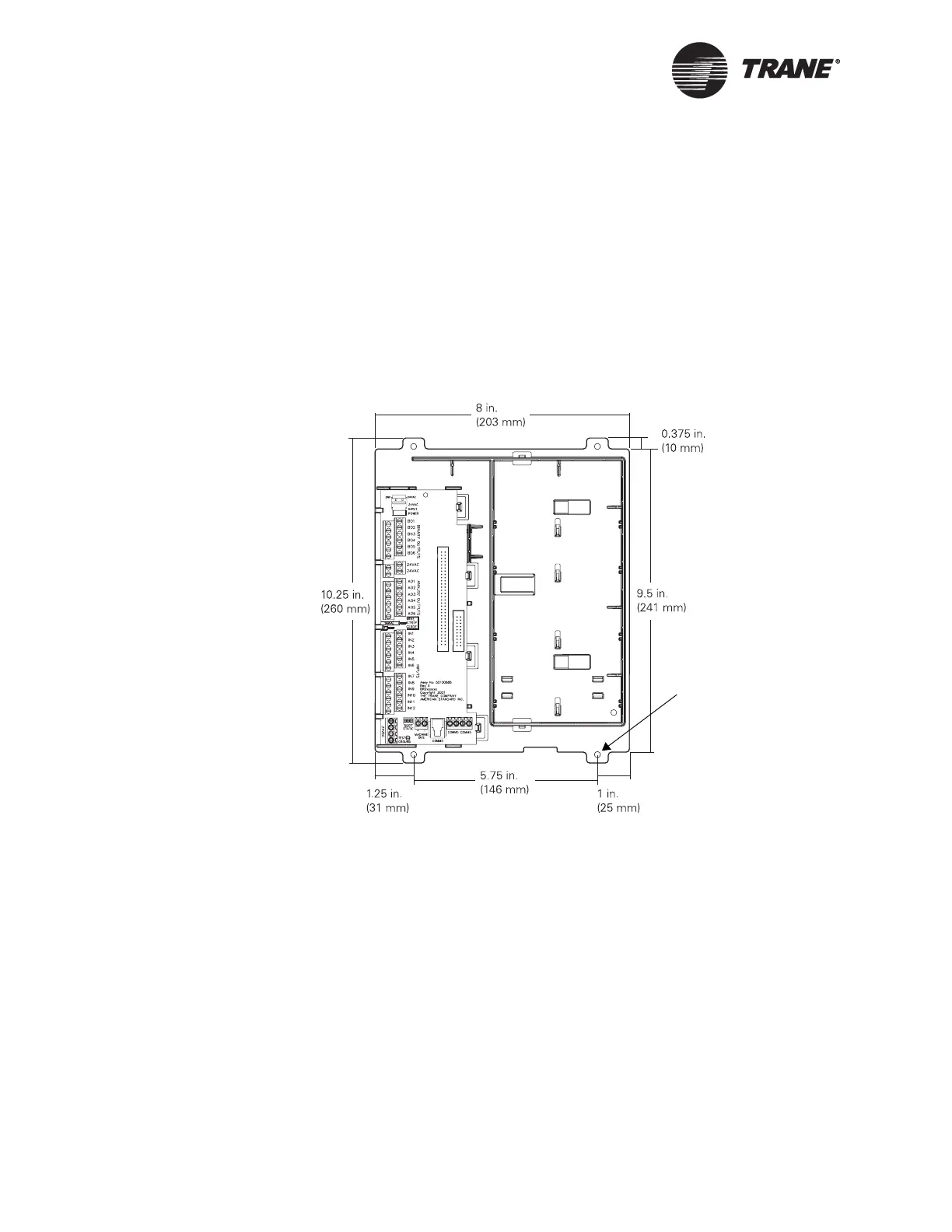
2. Using the bottom frame (with the termination board) as a template,
mark the location of the four mounting holes on the mounting surface
(see Figure 4).
Figure 4. Frame-mounted dimensions and mounting holes
3. Set the controller aside and drill holes for #8 (4 mm) screws at the
marked locations.
4. Secure the controller to the mounting surface with #8 (4 mm) screws
(not supplied).
To install input/output wires, the main circuit board, and other compo-
nents, follow the instructions in the following chapters.
Mounting holes
(four locations)

 Loading...


