Chapter 7 Wiring Comm5 links
46 CNT-SVN01C-EN
Comm5 zone sensor comm jack
Many Trane zone sensor models include a communication jack. When
properly wired to the communication terminals on the unit controller, the
communication jack provides easy access to both the controller and the
entire Comm5 link. This enables you to access the status and configura-
tion information of any controller on the link using the Rover service tool.
The recommended wire between the controller and the communication
jack is 22-gauge, Level 4 wire; or 18-gauge, shielded, twisted-pair with
stranded, tinned-copper conductors (Trane “purple” wire). Thermostat
wire is not recommended for the communication jack.
Zone sensor communication stubs
The wire that runs between the controller and zone sensor is commonly
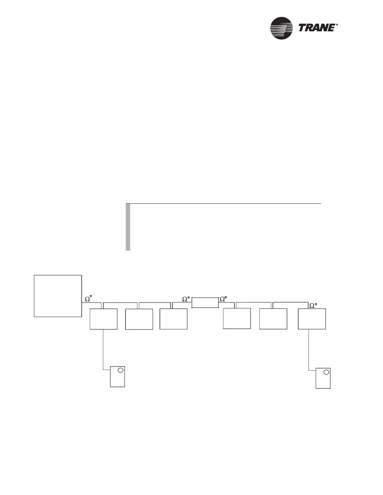
referred to as the communication stub. Figure 27 shows an example of
communication stubs on a Comm5 link when a repeater is used.
Figure 27. Communication stubs used with a repeater
Figure Note:
• Maximum wire length on either side of the repeater is 4,500 ft (1,400 m).
• The link repeater is limited to 60 devices on either side of the link.
• *Termination resistors placed at the end of each link. The resistance value of
the termination resistor is 105-ohm resistor for Level 4 wire at each end of the
link. For Trane “purple” wire use an 82-ohm resistor at each end of the link.
Note:
• Only 8 stubs can be used per Comm5 link. To add more
stubs to the link, a repeater is necessary. Up to 8 stubs may
be used on each side of the repeater (16 total stubs).
• Each communication stub must not exceed 50 feet in
length.
Repeater
C
o
m
m
s
t
u
b
C
o
m
m
s
t
u
b
System panel
Device
Device
Device
Device Device
Device

 Loading...


