EMI/RFI considerations
CNT-SVN01C-EN 51
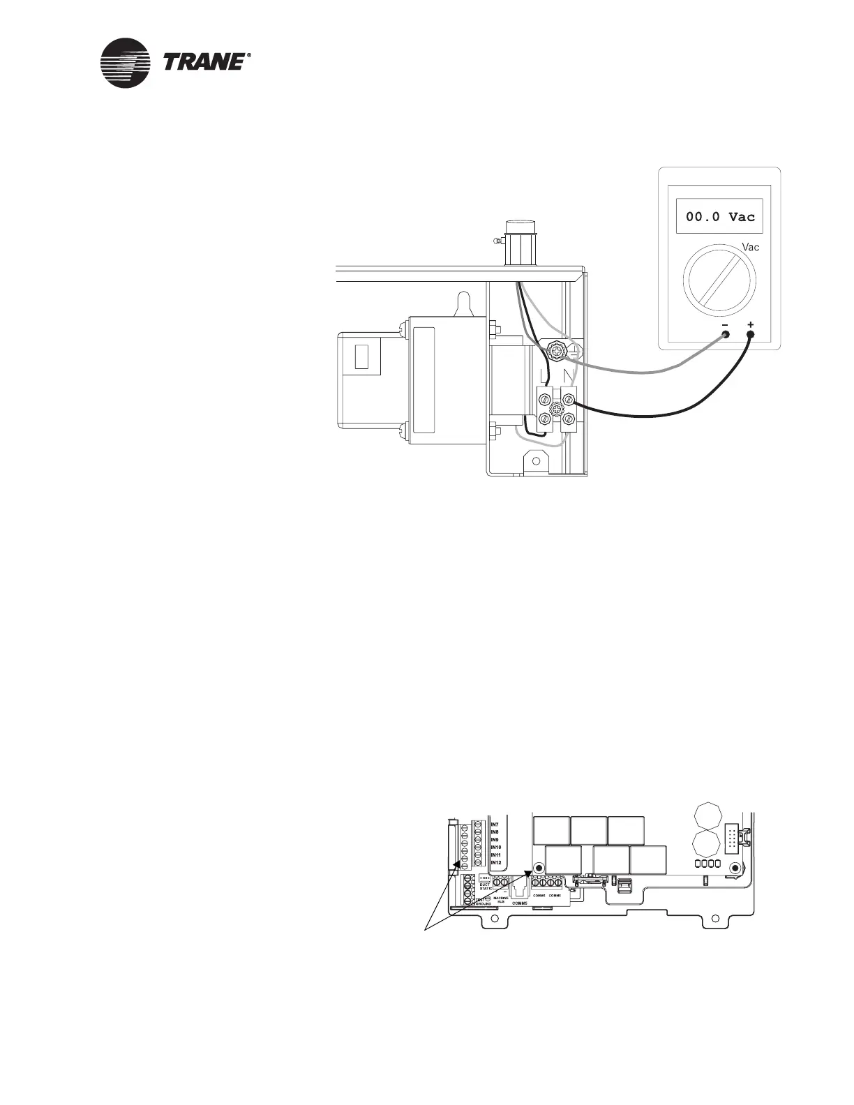
Figure 31. Checking the earth ground
Sectioning the shield on the Comm5 link
In areas with high RFI, you can section the Comm5 link shield between
Comm5 devices to reduce interference in the link.
To section the Comm5 link shield:
1. At the first Comm5 controller on the link, ground the shield to an
earth ground.
2. Where the link enters the Tracer MP581, cut back and tape the
shield.
3. Where the link leaves the Tracer MP581, ground the shield to an
earth ground.
The earth ground can be either a common terminal for any of the uni-
versal inputs or the lower-left mounting hole of the circuit board
(shown in Figure 32).
Figure 32. Grounding Comm5 wire
Grounding locations
for Comm5 wire

 Loading...


