CNT-SVN01C-EN 7
Chapter 2
Installing the frame-mounted
Tracer MP581
This chapter applies only to the frame-mounted Tracer MP581 controller.
You can use the frame-mounted Tracer MP581 to replace older controllers
in existing equipment or to mount in new equipment or custom
enclosures.
Enclosure requirements
Before installing the frame-mounted Tracer MP581, make sure that the
enclosure or mounting space meets the following minimum requirements:
• Minimum clearances as shown in Figure 3
• 24 Vac dedicated power supply
• Compliance with National Electrical Code and applicable local elec-
trical codes for high-voltage power wiring to the enclosure
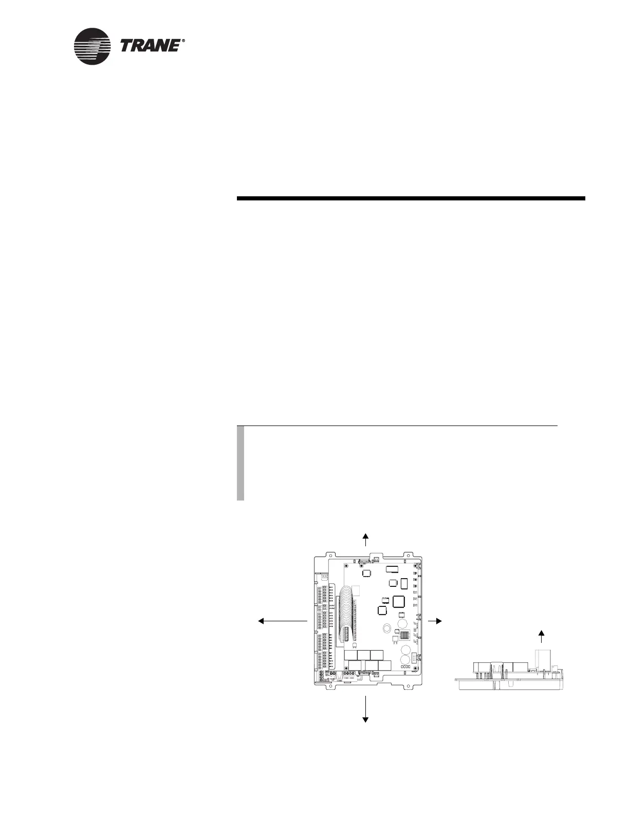
Figure 3. Frame-mounted Tracer MP581 minimum clearances
Note:
The Tracer MP581 with enclosure is mounted in a National
Electrical Manufacturers Association (NEMA) 1 enclosure. To
meet NEMA 4 specifications, you can order the frame-mounted
Tracer MP581 (model BMTM000CA0A0) and mount it in a
separately purchased NEMA 4 enclosure.
0.5 in. (13 mm)
0.5 in. (13 mm)
3 in. (76 mm)
for communications wires
6 in. (152 mm)
for I/O wires
0.5 in.
(13 mm)

 Loading...


