Wiring universal inputs
CNT-SVN01C-EN 23
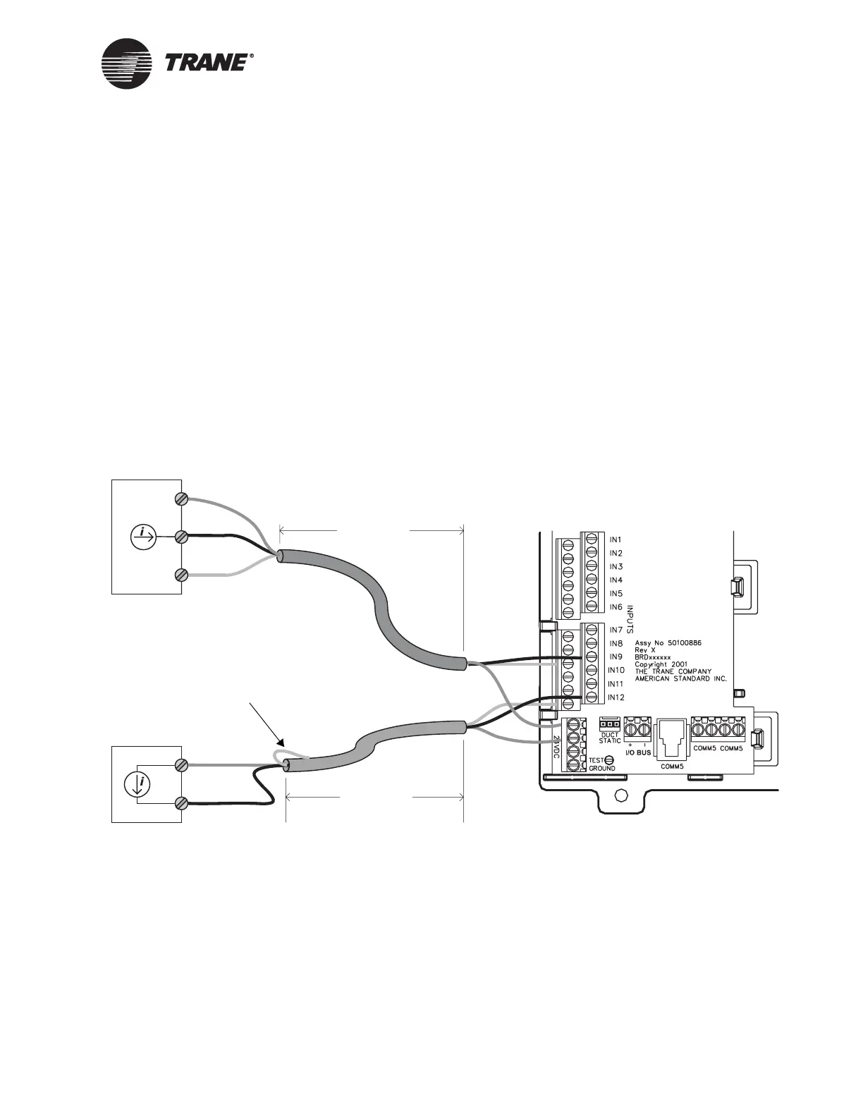
Wiring 0–20 mA analog inputs
Common 0–20 mA analog inputs include humidity sensors and pressure
sensors.
To wire a 0–20 mA analog input:
1. For three-wire applications, use a 3-conductor cable with a shield. .
For two-wire applications, use a 2-conductor cable with a shield. Con-
nect the shield to a common terminal at the termination board and
tape it back at the sensor (see Figure 14). Do not use the shield as the
common connection.
2. Connect the signal wire to an available input terminal (IN1–IN12).
3. Connect the supply wire to a 24 Vdc or 24 Vac terminal as required.
4. Use the Rover service tool to configure the input for analog operation.
Figure 14. Wiring 0–20 mA analog inputs
< 1000 ft
(300 m)
0–20 mA sensor
(current source)
24 Vdc
0–20 mA out
Common
0–20 mA sensor
(current controller)
< 1000 ft
(300 m)
Tape back shield
24 Vdc
0–20 mA out

 Loading...


