Chapter 5 Wiring inputs and outputs
20 CNT-SVN01C-EN
Screw-terminal locations
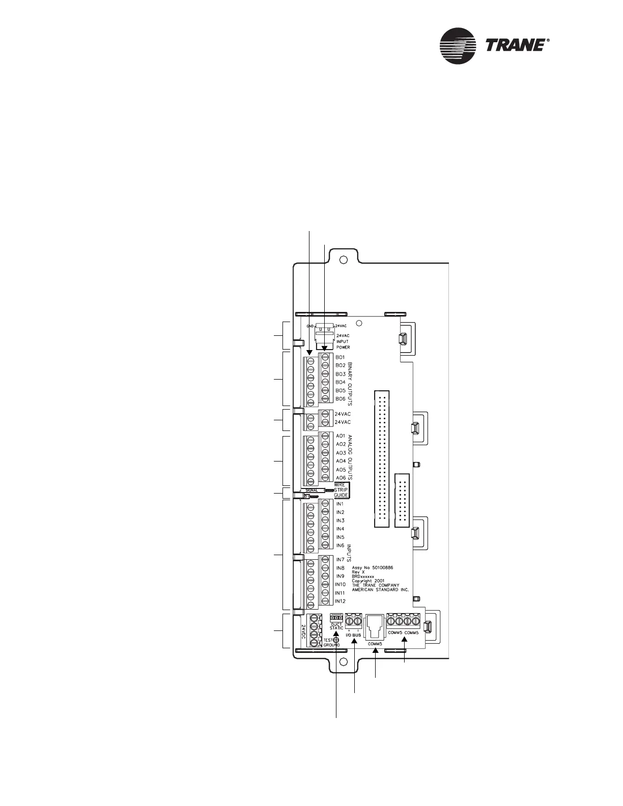
Figure 11 shows screw-terminal locations on the termination board. The
top row of screw terminals is for signal wires, and the bottom row of screw
terminals is for common wires. To make sure that the wires lie flat, use
the wire strip guide on the termination board to strip input/output wires
to the correct length.
Figure 11. Screw-terminal locations
Binary outputs
Common terminals
Signal terminals
24 Vac power
Analog outputs
Universal inputs
(IN1–IN4 can
accept RTDs)
Wire strip guide
24 Vdc power
Comm5 screw terminals
Comm5 jack for Rover service tool
I/O bus for EX2 expansion modules
(formerly labeled Machine Bus)
Duct-static pressure connector
24 Vac power
connector

 Loading...


