Chapter 5 Wiring inputs and outputs
24 CNT-SVN01C-EN
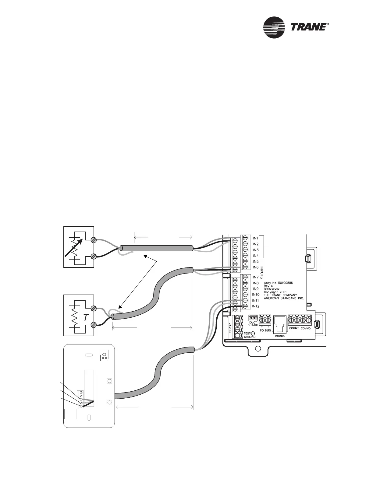
Wiring variable resistance analog inputs
Variable resistance analog inputs include 10K thermistors, resistance
temperature detectors (RTDs), and setpoint thumbwheels on zone
sensors.
IMPORTANT
The Tracer MP581 controller can accept RTDs only on inputs 1–4.
To wire a variable resistance analog input:
1. For three-wire applications, use a 3-conductor cable with a shield(see
Figure 15). For two-wire applications, use a 2-conductor cable with a
separate shield. Connect the shield to a common terminal board and
tape it back at the output device. Do not use the shield wire as a com-
mon connection.
2. Connect the signal wire to an available input terminal (IN1–IN12).
3. Use the Rover service tool to configure the input for analog operation.
Figure 15. Wiring variable resistance analog inputs
Variable resistance
Temperature sensor
< 300 ft
(100 m)
< 300 ft
(100 m)
Signal
Common
< 300 ft
(100 m)
Can accept
RTD inputs
Signal
Common
Trane zone
sensor
Common
Temperature
Setpoint
Tape back shield

 Loading...


