Chapter 15 Troubleshooting
88 CNT-SVN01C-EN
Analog output troubleshooting
If an analog output is not controlling the equipment wired to it, follow the
troubleshooting steps in Table 22. Perform the steps in the order they are
listed.
If the analog output is still not turning on the equipment wired to it, fol-
low the additional troubleshooting steps in Table 23. These steps will help
you assess the configuration and operation of the binary output.
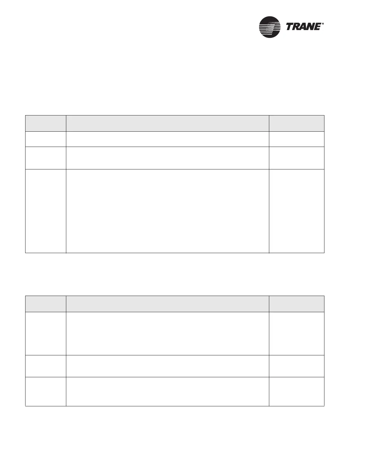
Table 22. Analog output troubleshooting of external wiring
Step number Action Probable cause
Step 1 Perform the initial troubleshooting steps described in Table 19 on page 86
and verify general board operation is okay.
General board
problem
Step 2 Inspect the wiring. Is there a good connection between the wire and the ter-
minal blocks? Look for shorts or opens. Pay particular attention to wire
splices.
Wiring problem
Step 3 For a 0–10 Vdc analog output, set the multi-meter to measure Vdc. Measure
across the analog output terminals. The valid range is from 0 Vdc to 10 Vdc.
Use either the operator display or the Rover service tool to override the
analog output to a known value.
For a 0–20 mA analog output, set the multi-meter to measure mA. This may
require that the meter connections be changed. Measure across the analog
output terminals. This effectively shunts all current through the multimeter. If
controlling an actuator, it should move to the 0 mA position. The valid range
is from 0 mA to 20 mA. Use either the operator display or the Rover service
tool to override the analog output to a known value.
For either type of output, set the multimeter to read Vac. Measure across the
analog output. The multimeter should show less than 0.1 Vac.
Wiring problem
Table 23. Analog output troubleshooting of configuration and operation
Step number Action Probable cause
Step 1 Connect the Rover service tool to the Comm5 communication link, start the
Rover service tool, and select the Tracer MP581 that you are troubleshooting
from the Active Group Tree. The device plug-in for the selected Tracer MP581
appears with the Active Device view displayed in the workspace.
See the Rover Operation and Programming guide, EMTX-SVX01D-EN, for
more information.
—
Step 2 If the analog output is on an EX2 expansion module, verify that communica-
tions are up between the Tracer MP581 and the expansion module. See the
Unit tab in the Status display for the Tracer MP581 in Rover.
Communication
failure with expan-
sion board
Step 3 Check the operating status to determine what is controlling the analog out-
puts. If the operator display or Rover is controlling the analog output, release
the override. If a program is controlling the analog output, use the debug
mode to investigate the program.
Override or pro-
gramming error

 Loading...


