Wiring universal inputs
CNT-SVN01C-EN 21
Wiring universal inputs
The Tracer MP581 controller has 12 universal inputs. Use the Rover ser-
vice tool to configure inputs for analog or binary operation.
The common terminals on the Tracer MP581 termination board are con-
nected to the metal enclosure by means of a ground screw. Shield wires
should be connected to a common terminal. Table 5 shows the load the
Tracer MP581 places on sensors.
Wiring binary inputs
Use binary inputs to monitor statuses, such as fan on/off and alarm
resets.
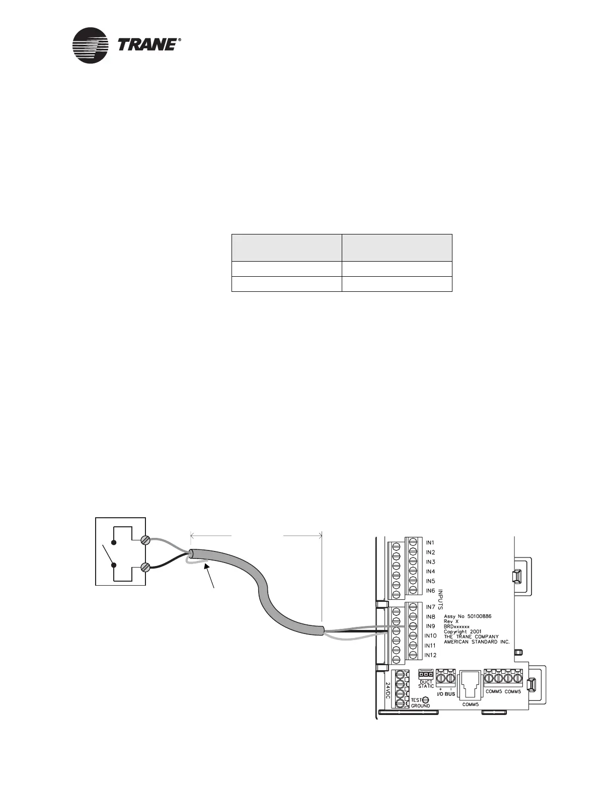
To wire a binary input:
1. Connect the common wire to a common terminal as shown in
Figure 12.
Note that because the common terminals are in parallel, you can wire
the common wire to any available common terminal.
2. Connect the shield wire to a common terminal at the termination
board and tape it back at the input device.
3. Connect the signal wire to an available input terminal (IN1–IN12).
4. Use the Rover service tool to configure the input for binary operation.
Figure 12. Wiring a binary input
Table 5. Load placed on sensors
Input type Load on sensor
Vdc (linear) 21 kΩ
mA (linear) 221 Ω
< 1000 ft
(300 m)
Binary switch
Signal
Common
Shield
Tape back shield

 Loading...


