Chapter 7 Wiring Comm5 links
42 CNT-SVN01C-EN
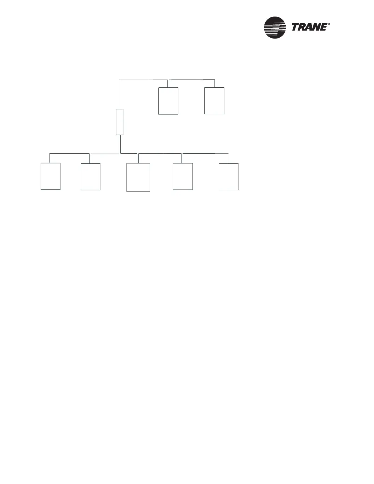
Figure 22. Alternate daisy chain configuration
Figure Note:
• Repeater with system panel in the middle of the link
• Maximum wire length for Comm5 is 4,500 ft (1,400 m) on each side of the
repeater
• For termination resistor placement, see “Termination resistance placement
for Comm5 links” on page 42
Termination resistance placement for
Comm5 links
Termination resistors are required at each end of Comm5 communication
daisy chain links.
To correctly place termination resistors follow these guidelines:
• Terminate a daisy chain configuration with a resistor at each end of
the link (see Figure 23 on page 43):
—22 AWG Level 4 wire 105
Ω, 1%, 1/4 Watt
—18 AWG Trane “purple” wire 82
Ω, 1%, 1/4 Watt
• If a repeater is used, each link of the configuration that is created by
the repeater requires termination resistors (see Figure 24 on
page 43).
• Trane recommends that only one type of wire be used for the Comm5
communication link.
• A set of as-built drawings or a map of the communication wire layout
should be made during installation. Any sketch of the communication
layout should feature the terminating resistor placement.
Repeater
Device
Device
Device
Device Device Device
System
panel

 Loading...


