Chapter 13 Installing EX2 expansion modules
76 CNT-SVN01C-EN
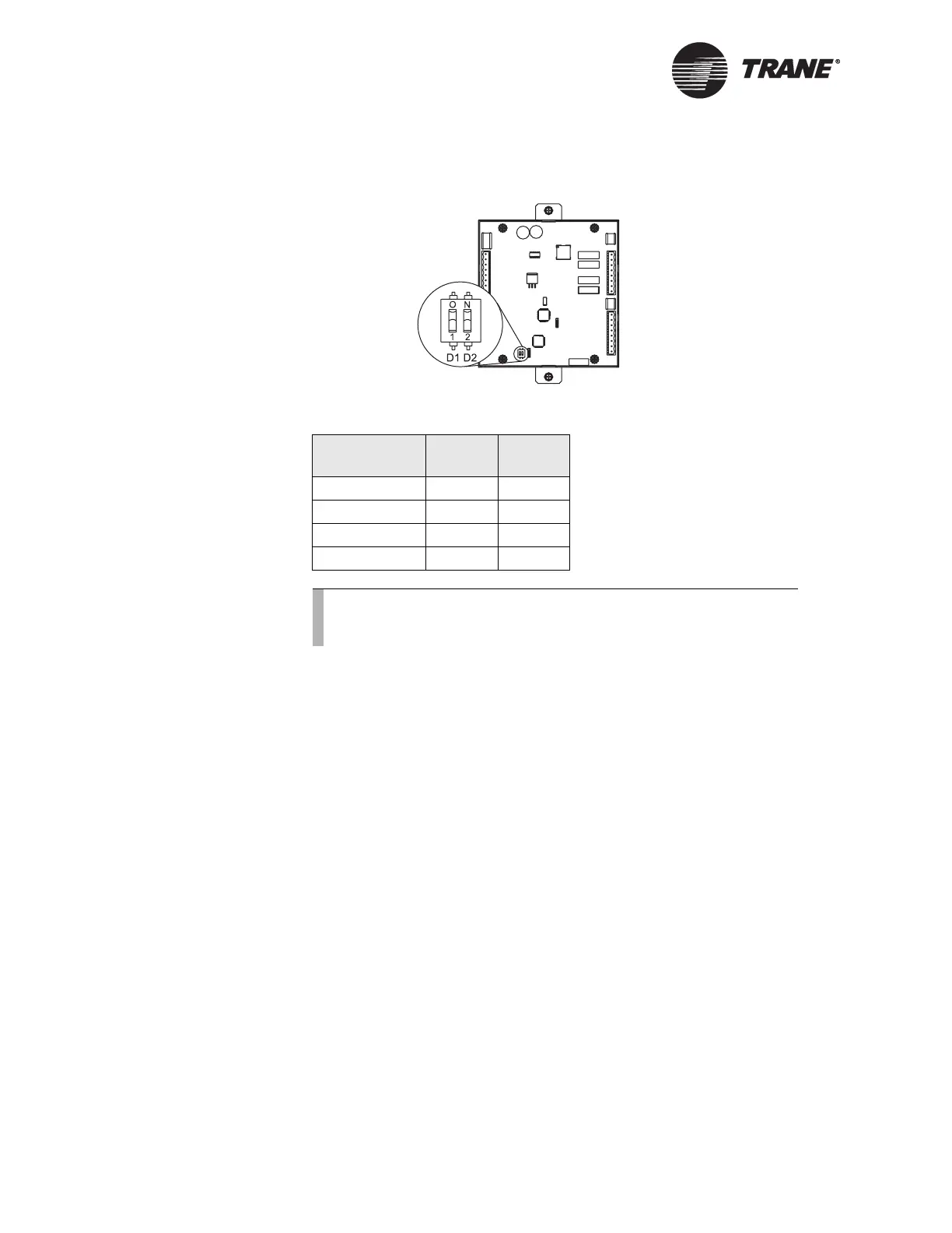
Figure 49. DIP switch on board
.
Input/output terminal wiring
All input/output terminal wiring for the EX2 module must meet the fol-
lowing requirements:
• All wiring must be in accordance with the National Electrical Code
and local codes.
• Use only 18–22 AWG, stranded, tinned-copper, shielded, twisted-pair
wire.
• Binary output wiring must not exceed 1,000 ft (300 m).
• Binary input and 4–20 mA input wiring must not exceed 1,000 ft
(300 m).
• Thermistor input, RTD input, and 0–10 Vdc input wiring must not
exceed 300 ft (100 m).
• Analog and 24 Vdc output wiring distances depend on the specifica-
tions of the receiving unit. Use shielding for analog and 24 Vdc
outputs.
• Do not run input/output wires in the same wire bundle with ac-power
wires.
The EX2 module has four binary outputs, four analog outputs, and six
universal inputs.
Table 10. EX2 DIP switch settings
EX2 module D1 D2
1OffOff
2OffOn
3OnOff
4OnOn
Note:
Cyle power to the EX2 (dipswitches can only be read during
power up).

 Loading...


