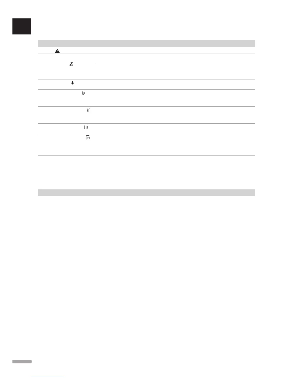
The table below shows problems that can occur in the digital thermostat T-149.
Indication Probable cause Solutions
Alarm icon is displayed
An error has occured Go to the alarm list for more information
The display is off
Communication icon is displayed in
the alarm list
The cable is not connected or a wire is
damaged.
Check the wiring
The thermostat is broken Force the thermostat to transmit by changing the
temperature setpoint
Replace the thermostat
Relative humidity icon is displayed
in the alarm list
The relative humidity limit is reached Lower the humidity level by increasing the ventilation or
temperature setpoint
Floor temperature sensor icon is
displayed in the alarm list
Faulty temperature sensor Check the connection of the floor sensor
Disconnect the floor temperature sensor and check it with an
ohmmeter. The value must be around 10 kohms
Outdoor temperature sensor icon is
displayed in the alarm list
Faulty temperature sensor Check the connection of the outdoor sensor
Disconnect the outdoor sensor and check it with an
ohmmeter. The value must be around 10 kohms
Indoor temperature sensor icon is
displayed in the alarm list
Faulty temperature sensor Contact the installer or replace the thermostat
Remote temperature sensor icon is
displayed in the alarm list
Faulty temperature sensor Contact the installer or replace the remote sensor
Disconnect the remote temperature sensor (if connected)
and check it with an ohmmeter. The value must be around
10 kohms
16.3 Analogue thermostat T-143 alarms/problems
An alarm is sent when more than 1 hour have elapsed since the controller received the last communication from the thermostat.
The table below lists problems that can occur in thermostats T-143.
Indication Probable cause Solutions
The channel LED on the controller
flashes
Tamper alarm is activated and a public
thermostat T-143 is removed from the wall
Check the thermostat settings and put it back on the wall
16.4 Contact the installer
For installer contact information, see the installation
report in the end of this document. Prepare the
following information before contacting an installer:
• Installation report
• Drawings of the underfloor heating system (if
available)
• List of all alarms, including time and date
16.5 Installer instructions
To determine if a problem is caused by the supply
system or the control system, loosen the actuators
from the manifold for the room concerned, wait a few
minutes and check if the flow pipe of the underfloor
heating loop becomes warm.
If the pipe does not become warm, the problem is in the
heating system. If the loop becomes warm, the cause
could be the room control system.
A supply system defect can be indicated by no warm
water in the manifold. Check the boiler and circulation
pump.
 Loading...