5.5 Connect components to controller
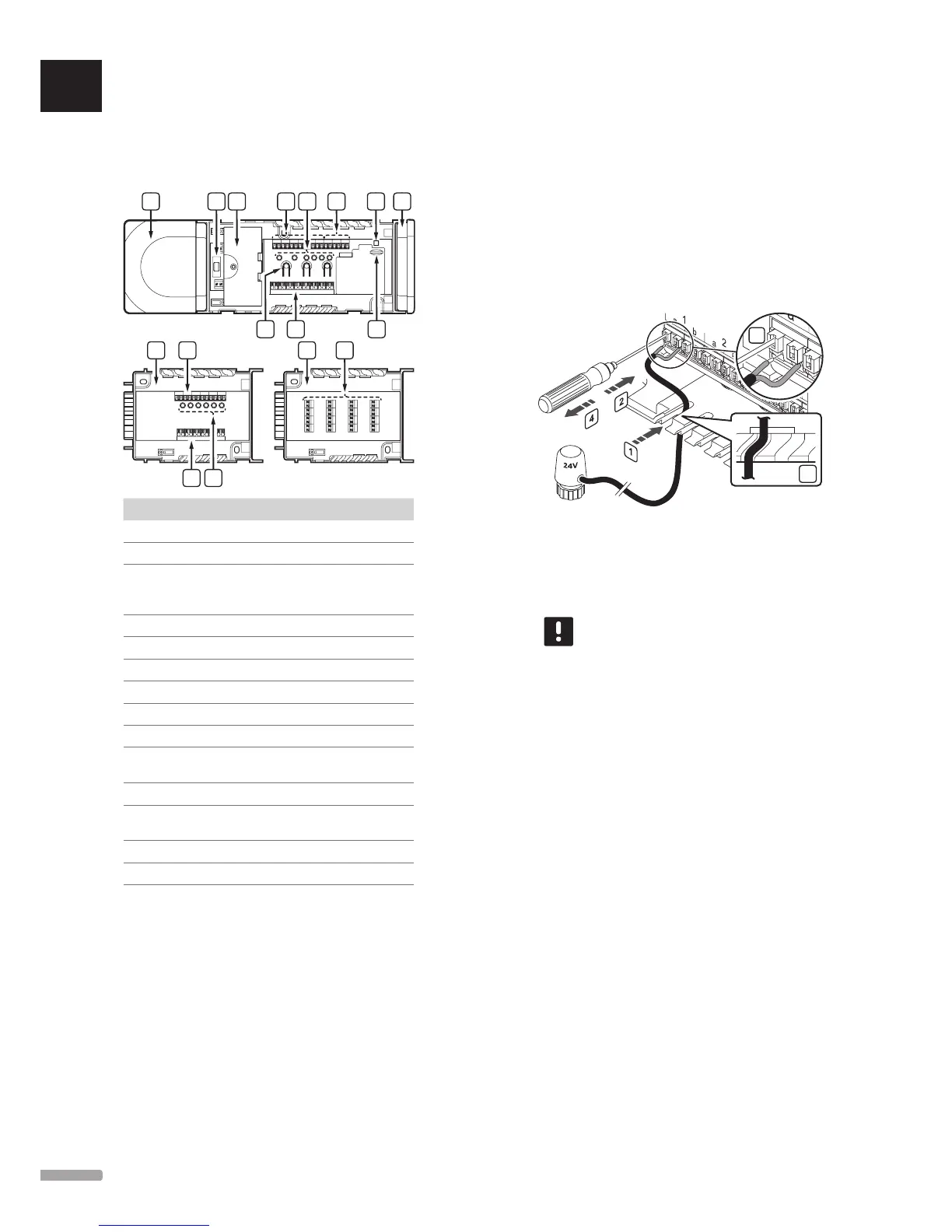
Refer to the wiring diagram found in the end of this
document. The illustration below shows the inside of
the controller.
Item Description
A Transformer, 230 V AC 50 Hz power module
B Fuse (T5 F3.15AL 250V)
C Optional inputs and outputs for pump, boiler
management, and heat pump connection (Base
PRO only)
D Channel registration buttons
E LEDs for channels 01 – 06
F Quick connectors for actuators
G Bus connection terminals
H System bus connection terminals (Base PRO only)
I Power LED
J Uponor Smatrix Base Slave Module M-140
(optional)
K LEDs for channels 07 – 12
L Uponor Smatrix Base Star Module M-141
(optional)
M End cap
N MicroSD card (Base PRO only)
Conne Ct aCtuators to Controlle r
Each thermostat can control one or more channels.
To simplify installation and maintenance, Uponor
recommends that actuators controlled by the same
thermostat shall be wired in sequence to the channels.
Connect the actuators to the controller as follows. Use
the figure below for guidance to the instructions.
1. Lead the cables from the actuators through cable
entries in the bottom of the controller frame. See
figure below.
1
3
2. Press, without turning, with a thin screwdriver, on
the white button of the quick connector.
3. Insert a wire in the quick connector.
4. Remove the screwdriver.
NOTE!
Identify the room supplied by each loop on
the manifold and determine which channel it
must be connected to.
UK
CZ
DE
DK
EE
ES
FI
FR
HR
HU
IT
LT
LV
NL
NO
PL
PT
RO
RU
SE
SK
UPONOR SMATRIX BASE/BASE PRO · INSTALLATION AND OPERATION MANUAL
 Loading...