Conne Ct Co mmu niC atio n C a Ble to Co ntroller
2
3
3
A-AB B-
1
1
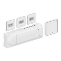
To connect a communication cable to the controller:
1. Lead the cables through cable entries on the top of
the controller frame.
2. Insert two wires (A,B), the - wire is optional
and only used in some cases, into a free system
connector (one of the rightmost connectors) on the
controller.
3. Tighten the screws fixing the wires in the connector.
4. Cut and stow away unused wires.
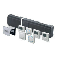
Conne Ct Commun iCation CaBl e to interfaCe
Wall BraCKet
A
B
-
To connect a communication cable to the wall bracket:
1. Lead the cables through the wall socket.
2. Insert two wires (A,B), the - wire is optional and
only used in some cases, into the connectors on the
wall bracket.
3. Tighten the screws fixing the wires in the connector.
4. Cut and stow away unused wires.
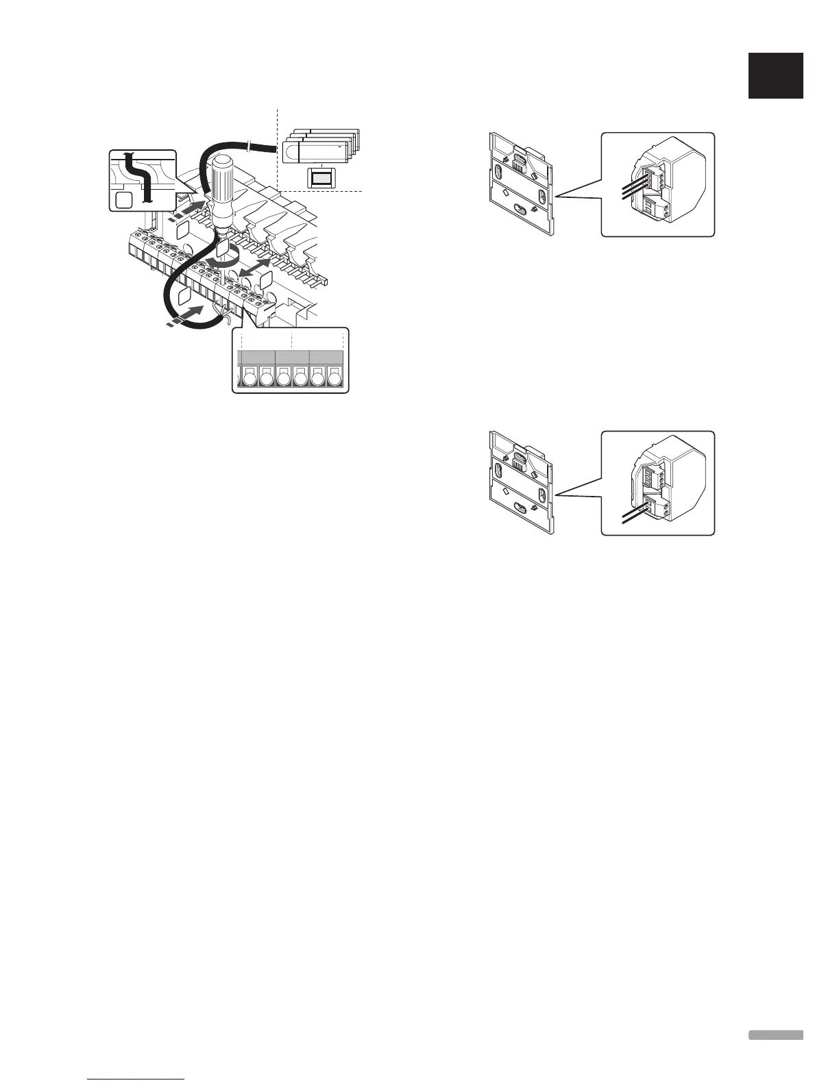
Conne Ct PoW er to the interfaCe Wall BraCKet
N
L
To connect power to the wall bracket:
1. Lead the cables through the wall socket.
2. Insert the two wires (L and N) into the
corresponding connectors on the wall bracket.
3. Tighten the screws fixing the wires in the connector.
UK
CZ
DE
DK
EE
ES
FI
FR
HR
HU
IT
LT
LV
NL
NO
PL
PT
RO
RU
SE
SK
UPONOR SMATRIX BASE/BASE PRO · INSTALLATION AND OPERATION MANUAL
 Loading...