During normal operation a discreet LED on back of
the thermostat is lit for about 60 seconds if there is a
demand for heating or cooling.
The thermostat contains a switch that, if activated
during registration, sends an alarm when the thermostat
is removed from the wall. The alarm is transmitted
through the connected cables, causing the related
channel LED on the controller to flash.
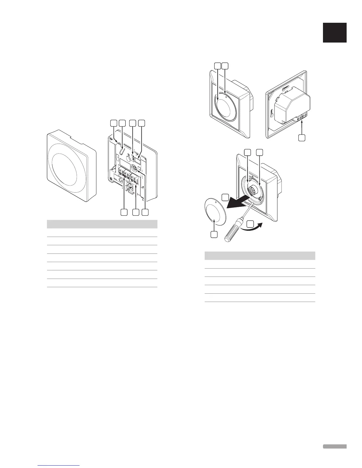
The illustration below shows the parts of the
thermostat.
Item Description
A Setpoint temperature potentiometer
B Registration button
C Disable timer switch
D Terminal for external sensor (non-polarised)
E Configuration DIP switches
F Terminal for communication cable
G Heating/cooling demand LED
A
1
2
Item Description
A Room temperature setpoint dial control
B Heating/cooling demand LED
C Registration button
D Disable timer switch
E Terminal for communication cable
 Loading...