DS1093-162A 12
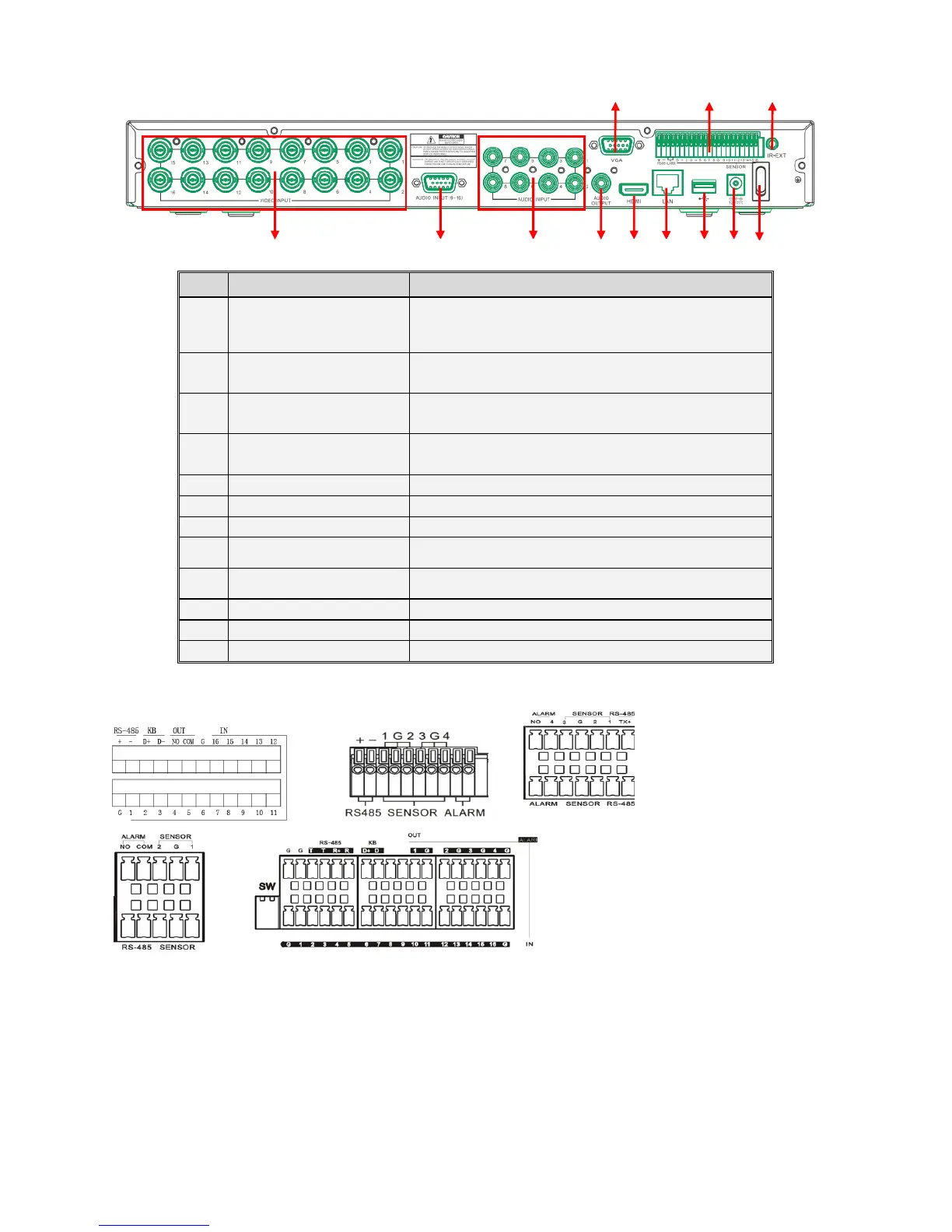
1.5.4 REF. 1093/526-528 DVR BACK PANEL
Item Physical port Connection method
1
Video inputs
Connect CH1-CH16 (Virtual) video input device (BNC
interface)
2 Audio Inputs 8CH audio input CH1-CH8 (RCA interface)
3
Audio Inputs
Connector for audio cable with audio inputs CH9-CH16
(RCA)
4
Audio Output Audio output (RCA interface);
5
USB Port
Connect USB mouse
6
HDMI Port
Connect to HDMI monitor
7
VGA Port
Connect to VGA monitor, such as PC monitor
8
PIN RS485/ Sensor Alarms RS485/Sensor/Alarm interface (see pin outs below)
9
IR-EXT For IR ext Remote Control (for future use)
10
Power Port
Connect power supply - DC12V 5A
11
Ethernet Port
Connect LAN, Ethernet (RJ45 interface)
12
Power Switch
Turn Power on and off
1.5.5 RS485/SENSOR/ALARM PORT FUNCTIONS
Alarm input: Connect [-] port of your sensor to G (GND) pin, and [+] port to channel input according to the alarm device
you purchased.
Alarm output: Connect to the two ports marked with “out”
PTZ Port: Connect your camera to RS-485A and RS485B accordingly.
KB PIN not available.
4
9
10
8
2
1 12
6
11 5
3
7
 Loading...