INSTALLATION
Series 613
16/149
Edition 12.08.2022 984360EC
5.3.1 Installation Hints
Install valve into the vacuum system. Valve seat side shall face process chamber.
•
Do not tighten the flange screws stronger than indicated under chapter «Tightening
torque».
•
Do not admit higher forces to the valve than indicated under chapter «Admissible
forces».
•
Make sure that enough space is kept free to do preventive maintenance work. The
required space is indicated on the dimensional drawing.
•
Control unit of valves with ISO-KF (61. . . – K . . .) needs support when mounted
on horizontal piping and control unit does not hang.
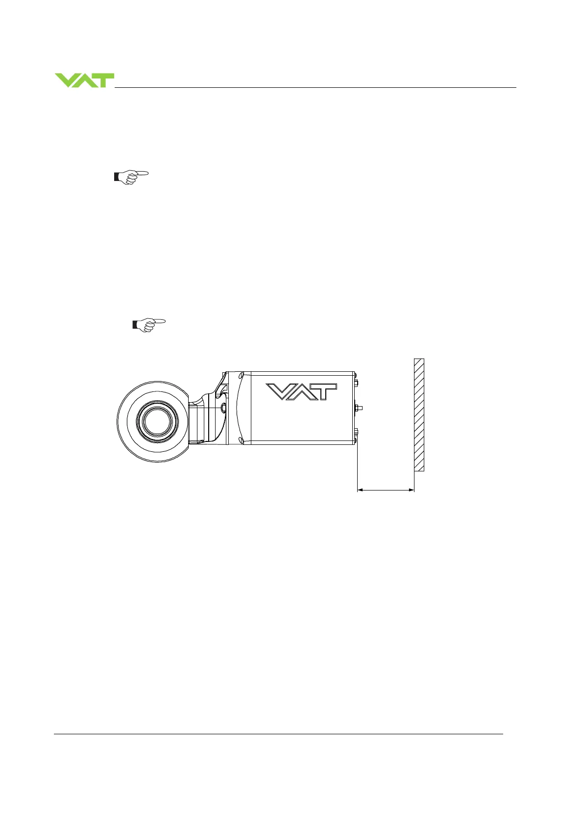
5.3.2 Installation space condition
Install the valve with integrated controller with space for dismantling and air
circulation as shown in figure below.
Sample picture
70

 Loading...


