INSTALLATION
Series 613
20/149
Edition 12.08.2022 984360EC
5.3.6 Tightening torque DNs 63 – 100mm
Tighten mounting screws of the flanges uniformly in crosswise order. Observe the maximum torque levels
in the following table. Higher tightening torques deforms the valve body and may lead to malfunction of
the valve.
5.3.6.1 Mounting of CF-F flanges
Tightening torques for CF-F flange connections depend on the type of seal which is used. Follow
recommendations of seal manufacturer.
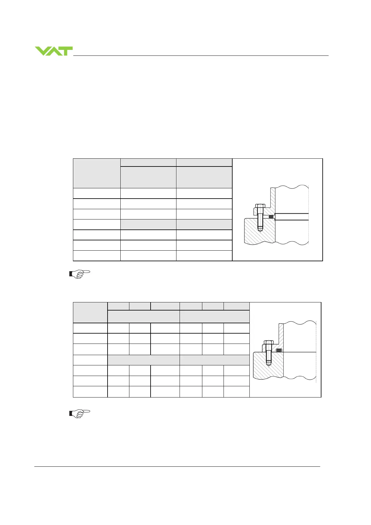
5.3.6.2 Mounting with centering rings
Valve size
ISO-F ISO-F
max. tightening
torque
(Nm)
max. tightening
torque
(lbs . ft)
DN63 / 2½ “ 8-10 6-8
DN80 / 3“ 8-10 6-8
DN100 / 4“ 8-10 6-8
hole depth (mm) hole depth (inch)
DN63 / 2½ “ 12 0.47
DN80 / 3“ 12 0.47
DN100 / 4“ 12 0.47
5.3.6.3 Mounting with O-ring in grooves
Valve size
ISO-F JIS ASA-LP ISO-F JIS ASA-LP
max. tightening torque
(Nm)
max. tightening torque
(lbs . ft)
DN63 / 2½ “
20-23
35-40
35-40 15-17 26-30 26-30
DN80 / 3“ 20-23
35-40
35-40 15-17 26-30 26-30
DN100 / 4“ 20-23
35-40
35-40 15-17 26-30 26-30
hole depth (mm) hole depth (inch)
DN63 / 2½ “
12 n/a n/a 0.47 n/a n/a
DN80 / 3“ 12 n/a n/a 0.47 n/a n/a
DN100 / 4“ 12 n/a n/a 0.47 n/a n/a
Refer to «Spare parts / Accessories» for centering rings ordering numbers.
Make sure that screws in use are capable to withstand applied torques.

 Loading...


