Vertiv | SmartAisle2 | User Manual 99
Installation
2.13. Installation of the Monitoring System
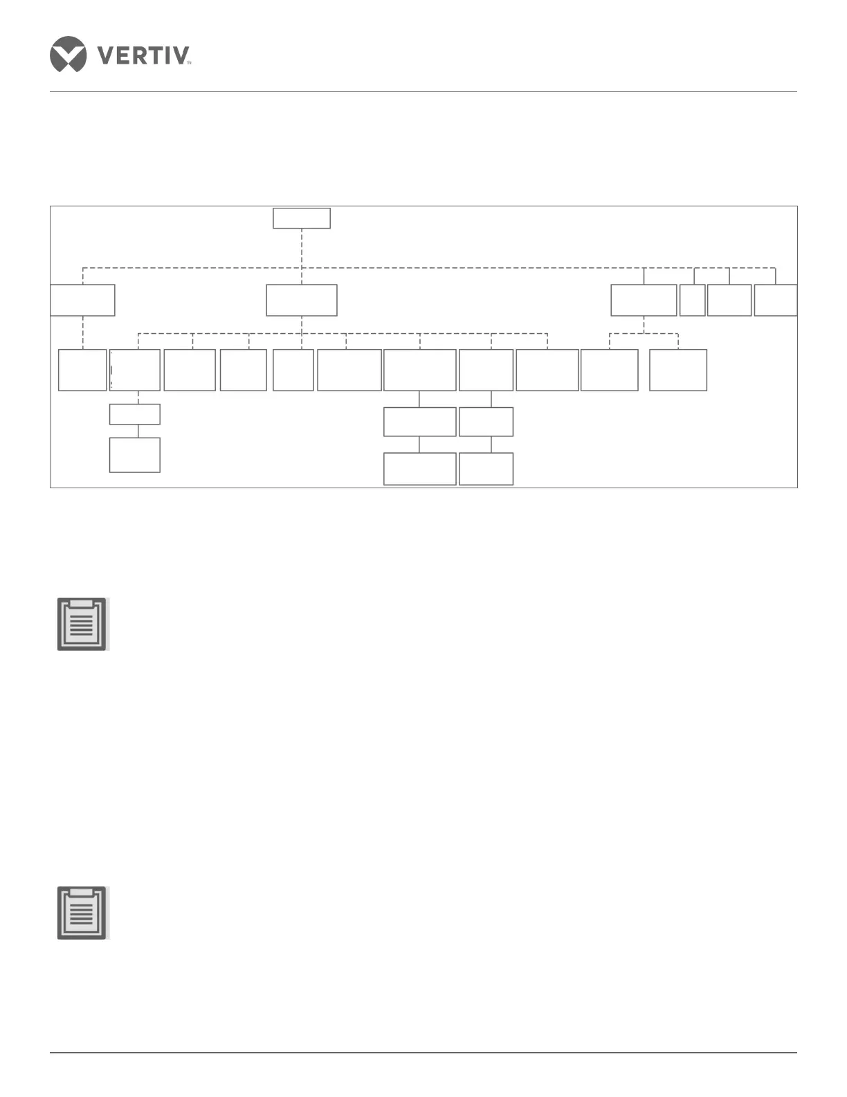
2.13.1. Monitoring Architecture
Figure 2-110 Monitoring Architecture
2.13.2. Installation RDU-M
RDU-M is fitted with a control panel on the nearest side of the IT Racks.
• The RDU-M 39U is mounted on the second host in the recommended space. The layout of the equipment
within the enclosure may be selected in the first upper space 37U to 41U based on the area.
• For the RDU-M installation, refer to the specific user manual.
2.13.3. Installing the Switch
The switch is mounted in the IT rack space where the RDU-M is placed. Refer to the switch user manual for the
installation methods.
2.13.4. RDU-A G2 and installing the Expansion Cards
RDU-A G2 is mounted in the IT Racks where the RDU-M is placed with a 4 COM card insertion slot 1; 8 DO/AO
card is inserted in the slot 2.
• RDU –A G2 at the host is recommended to be installed in the 40U space; 37U may be the first region to an
upper space of 41U for the cabinet apparatus based on the selected layout.
• Detailed installation requirements for RDU-A G2 can be referred to the user manual on RDU-A G2 wherein
things are explained in great detail to enable users to get to grips with the installation process.
Switch
RDU-M RDU-A
Display
Panel
Temp &
Humidity
Sensor
Leakage
Sensor
Infrared
Sensor
Roof
Status
Sensor
Audible &
Visual Alarm
Lamp
Opening
Controller
Roof Open
Button
Roof Elec-mag
Lock
Lighter
Lighting
Switch
Lighting
Controller
Power
Distribution
Access
Card
Reader
Door Open
Button
Access
Controller
Camera
CoolingNVR
4DI
Auto
Door

 Loading...


