Vertiv | SmartAisle2 | User Manual 114
Operation & Display Panel
Types of
parameters
Checklist items
Test
result
Roof open
The power switch on the controller is properly connected
Removing the need to open the top plate fixing screws
Ensure electromagnetic lock suction plate locking screws does not ensure fluctuation absorbing
plate may have activity
Monitor Check to make sure the entire communications network lines correct line sequence
• The authorized technicians check all the conditions that prohibit the power user.
• Input switching points before the closing operation – ensure that the input power is completely disconnect-
ed SPM.
3.2. Power
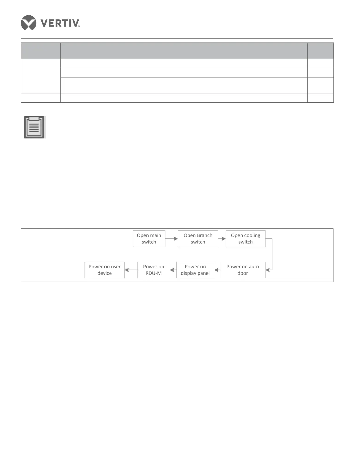
To power up a SmartAisle2 refer the flowchart in Figure 3-1.
Before booting up the SmartAisle, kindly contact the customer service telephone (#400) to initiate boot
authorization and carry out the following steps:
Figure 3-1 Power Flowchart
Following steps need to be adhered as per the power flow:
1. External input power switch of the distribution cabinet must be closed; the operation display panel lights of
the power distribution cabinet should be lit.
2. Closing arm switching the air conditioner distribution cabinet; able to switch rack PDU too.
3. The main switch is closed and at the lower stage switching the air conditioning indoor and the outdoor unit
switch occurs to confirm if the air conditioner is operating normally.
4. Electric door switch is close and the electric door self-test is performed to observe if the operation observed is
normal.
5. Open the control panel power button to ascertain if normal operation is observed.
6. Open the power button RDU-M in the running state of the control system to check if normal operation is
observed.

 Loading...


