Vertiv | SmartAisle2 | User Manual 19
Installation
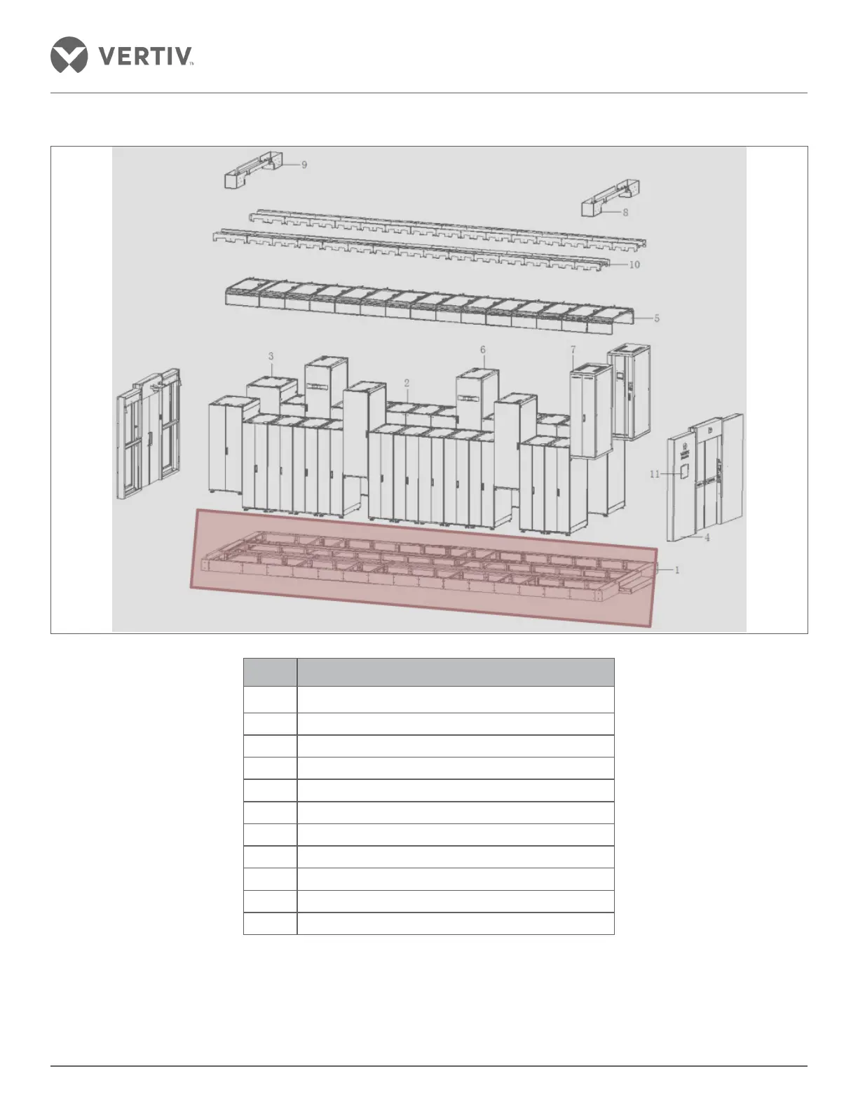
2.4.1. Installation of the base
Sl. No. Details of Equipment
1 Base
2 Server Cabinet
3 Network Cabinet
4 Access door
5 Top Plate
6 A/C Column
7 Distribution Cabinet
8 Strong wire passage groove
9 Power cable trunking; copper and fiber cable tray
10 Cabinet top wire groove
11 Control panel
• The three parts connected and coupled in steps are the door susceptor by a channel base and the left and
right channels of the base door as shown in Figure 2-5.

 Loading...


