5-4 IM 760401-01E
5.3 Displaying the Phase Angle
Keys
CHECK RANGE
MODE
UPDATE
SCALING
AVG
LINE FREQ
STORE RECALL
HARMONICS
KEY LOCK
FILTER
A
B
C
VOLTAGE VOLTAGE
VOLTAGE
AUTO
MODE
CURRENT
AUTO
RANGE
MAX HOLD
TRIG
CAL
INTEGRATOR
INTEG SET
SHIFT
KEY LOCK
1P 3W
3P 3W
3P 4W
3V 3A
OUTPUT
HARMONICS
MEMORY
REMOTE
MEAN
CURRENT RMS
DC
FUNCTION
ELEMENT
MAX HOLD
HOLD
ENTER
RESET
WIRING
START STOP
LOCAL
SETUP
1
m
V
k
A
V
TIME
ar
deg
h
h
VA
MW
m
VPF
k
A
MW
m
VHz
k
A
MW
23
FUNCTION
ELEMENT
123
FUNCTION
ELEMENT
123
%
The explanation given in this section uses WT230 as an example. For the differences between
the WT210 and the WT230, see section 2.2, “Operation Keys and Functions/Element Display.”
Procedure
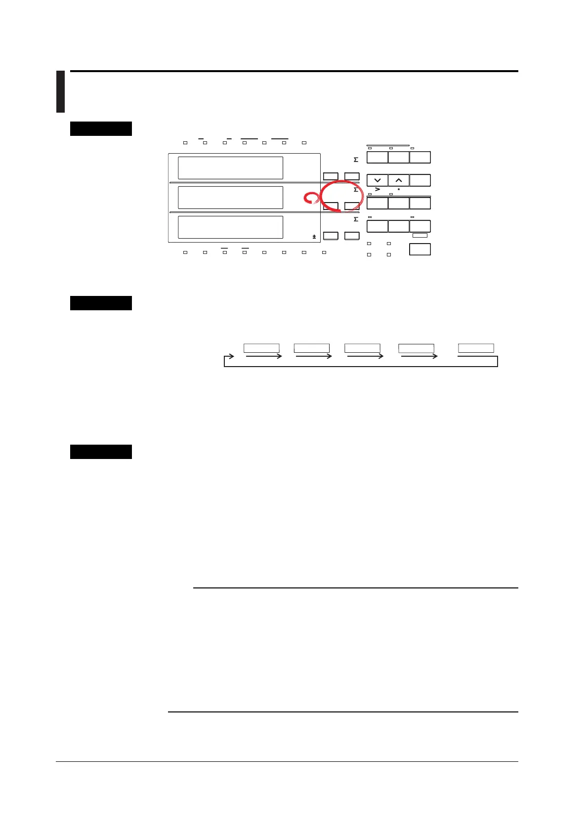
1. Selecting the Display Function
Select deg (phase angle) by pressing the FUNCTION key of display B.
Display
B
deg
FUNCTION FUNCTION FUNCTION
FUNCTION
FUNCTION
You can reverse the order by first pressing the SHIFT key followed by the FUNCTION key.
2. Selecting the Input Element
Select the input element by pressing the ELEMENT key of display B. The operation is
the same as the one described on page 5-1.
Explanation
Display Range and Unit
• Display range: G180.0 to d180.0 (G meaning phase lag, d meaning phase lead)
• Unit: deg
Selecting the Display Function
When you select deg, the phase angle will be displayed.
Selecting the Input Element
• 1/2/3: Displays the measurement values of element 1/2/3
• Σ: Refer to page 5-2.
Note
• Changing the measurement mode might result in different computed results, even when the
input signal is the same. For more details on the measurement mode, refer to page 4-1.
• When either the voltage or current drops below 0.5% (less than or equal to 1% if the crest
factor is set to 6) of the measurement range, dEGErr will be displayed.
• Distinction between phase lag and lead can be made properly, only when both voltage and
current are sine waves, and when the percentage of voltage or current input relating to the
measurement range does not fluctuate much.
• If the computed result of the power factor exceeds 1, the display will be as follows.
• Between 1.0001 to 2.0000 or –1.0001 to –2.0000: the phase angle displays 0.0
• 2.0001 or more or –2.0001 or less: the phase angle displays dEGErr.

 Loading...


