3-11
IM 760401-01E
Before Starting Measurements
3
3.7 Directly Wiring the Circuit under Measurement
WARNING
When measuring current by directly applying the current to flow through the
current input terminals of the WT210/WT230, the voltage of the object to be
measured appears at the external sensor input connector. To prevent the
possibility of electric shock, remove the cable for measurements from the
external sensor.
CAUTION
The measurement current flows through the thick lines in the figure below. Use
wires with sufficient current capacity.
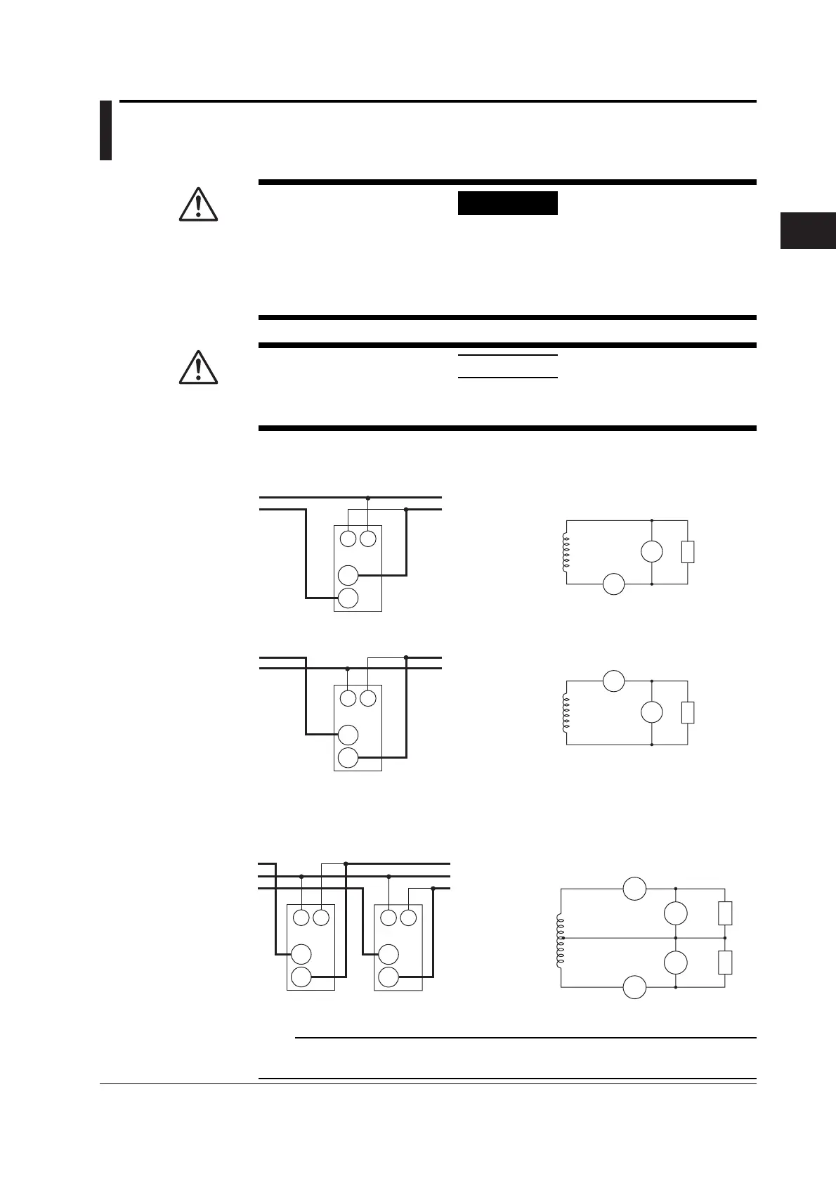
Wiring example of a single-phase, two-wire system (1P2W) ... Can be applied to
models 760401, 760502, and 760503.
Source
Load
C
±
±
Input termonal
(Element)
V
V : VOLTAGE terminal
C : CURRENT terminal
Source
Load
C
±
±
Input terminal
(Element)
V
V : VOLTAGE terminal
C : CURRENT terminal
Source
Load
V
A
±
±
C
V
Source
Load
V
A
±
±
C
V
Wiring example of a single-phase, three-wire system (1P3W) ... Can be applied to
models 760502, and 760503.
±
±
C
V
±
V
±
C
N
Source
Source
Load
Load
C
±
±
Input terminal
(Element 1)
V
V : VOLTAGE terminal
C : CURRENT terminal
N
C
±
±
Input terminal
(Element 3)
V
V1
V3
A3
A1
Note
It is recommended that the wire connected from the source to the ± current terminal be routed
as close as possible to the ground potential in order to minimize measurement error.

 Loading...


