4-5
IM 760401-01E
Setting Measurement Conditions and Measurement Range
4
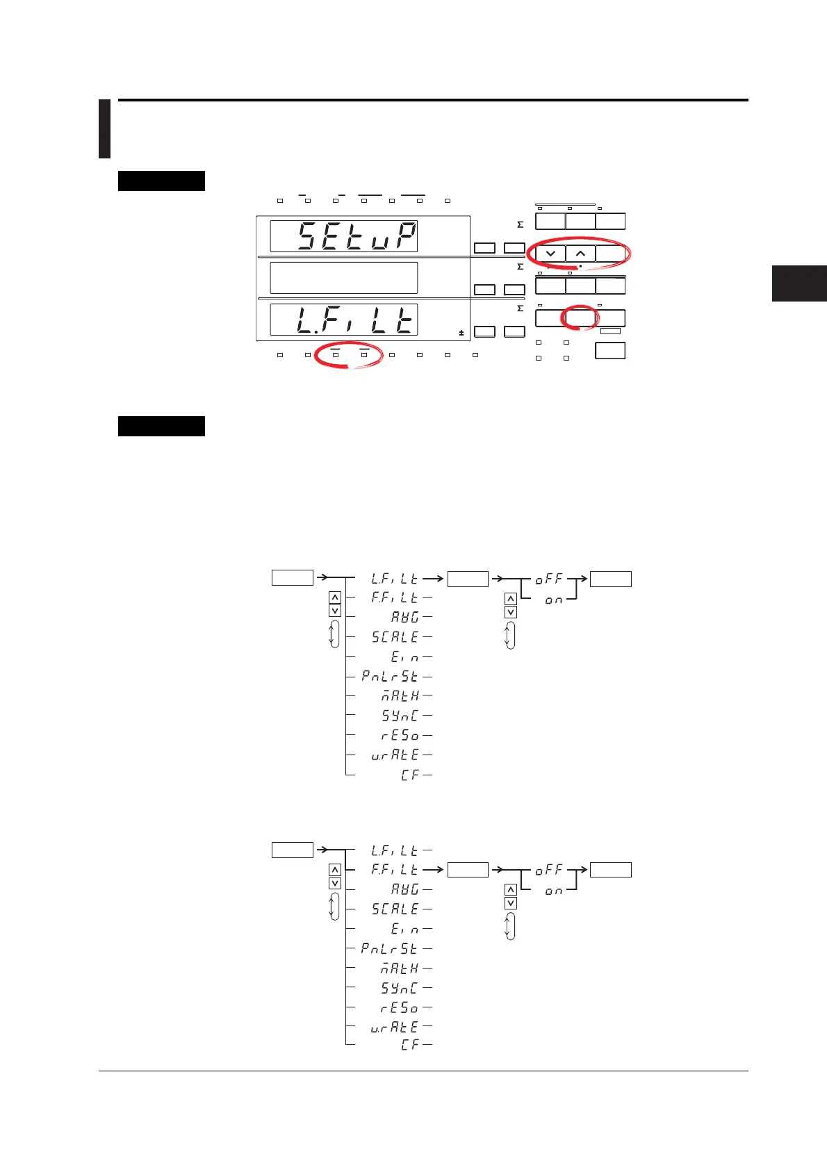
4.3 Turning ON/OFF the Input Filter
Keys
CHECK RANGE
MODE
UPDATE
SCALING
AVG
LINE FREQ
STORE RECALL
HARMONICS
KEY LOCK
FILTER
A
B
C
VOLTAGE VOLTAGE
VOLTAGE
AUTO
MODE
CURRENT
AUTO
RANGE
MAX HOLD
TRIG
CAL
INTEGRATOR
INTEG SET
SHIFT
KEY LOCK
1P 3W
3P 3W
3P 4W
3V 3A
OUTPUT
HARMONICS
MEMORY
REMOTE
MEAN
CURRENT RMS
DC
FUNCTION
ELEMENT
MAX HOLD
HOLD
ENTER
RESET
WIRING
START STOP
LOCAL
SETUP
1
m
V
k
A
V
TIME
ar
deg
h
h
VA
MW
m
VPF
k
A
MW
m
VHz
k
A
MW
23
FUNCTION
ELEMENT
123
FUNCTION
ELEMENT
123
%
The explanation given in this section uses WT230 as an example. For the differences between
the WT210 and the WT230, see section 2.2, “Operation Keys and Functions/Element Display.”
Procedure
• Operate the instrument by following the thick lines in the menu below.
• Press the ENTER key to confirm a selection or setting.
• To leave the current menu in the middle of the operation, press the key indicated in
step 1. The confirmed settings up to that point are kept.
Turning ON/OFF the Line Filter
ENTER
3.
ENTER
( Display C )
4.
5
.
End of setting
Select the filter function
( Display C )
SETUP
1.
2.
Turning ON/OFF the Frequency Filter
ENTER
3.
ENTER
( Display C )
4.
5
.
End of setting
Select the filter function
( Display C )
SETUP
1.
2.

 Loading...


