12-5
IM 760401-01E
Initializing Setup Parameters, Zero-Level Compensation,
and Key Lock
12
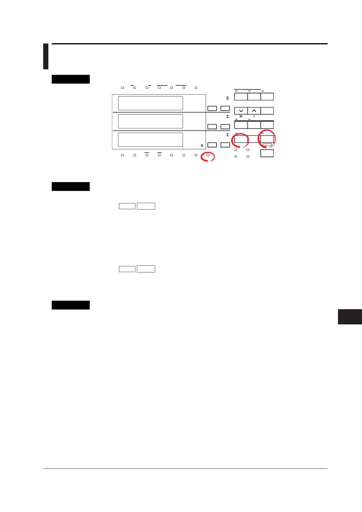
12.4 Key Lock
Keys
CHECK RANGE
MODE
UPDATE
SCALING
AVG
LINE FREQ
STORE RECALL
HARMONICS
KEY LOCK
FILTER
A
B
C
VOLTAGE VOLTAGE
VOLTAGE
AUTO
MODE
CURRENT
AUTO
RANGE
MAX HOLD
TRIG
CAL
INTEGRATOR
INTEG SET
SHIFT
KEY LOCK
1P 3W
3P 3W
3P 4W
3V 3A
OUTPUT
HARMONICS
MEMORY
REMOTE
MEAN
CURRENT RMS
DC
FUNCTION
ELEMENT
MAX HOLD
HOLD
ENTER
RESET
WIRING
START STOP
LOCAL
SETUP
1
m
V
k
A
V
TIME
ar
deg
h
h
VA
MW
m
VPF
k
A
MW
m
VHz
k
A
MW
23
FUNCTION
ELEMENT
123
FUNCTION
ELEMENT
123
%
The explanation given in this section uses WT230 as an example. For the differences between
the WT210 and the WT230, see section 2.2, “Operation Keys and Functions/Element Display.”
Procedure
• Turning ON the key lock
SHIFT
KEY LOCK
LOCAL
(Key lock ON)
The KEY LOCK indicator on the front panel illuminates. From this point, you can only
operate the power switch or carry out the operation to turn OFF the key lock.
• Turning OFF the key lock
Carry out the following procedure while the KEY LOCK indicator is lit.
SHIFT
KEY LOCK
LOCAL
(Key lock OFF)
The KEY LOCK indicator on the front panel turns OFF. All key operations are
enabled.
Explanation
Key Lock
You can disable (key lock) the front panel key operation. However, the following
switch and key operations are enabled even during key lock.
• ON/OFF of the power switch
• Operation to turn OFF key lock

 Loading...


