1-1
IM 760401-01E
Functional Overview and Digital Display
1
Chapter 1 Functional Overview and Digital Display
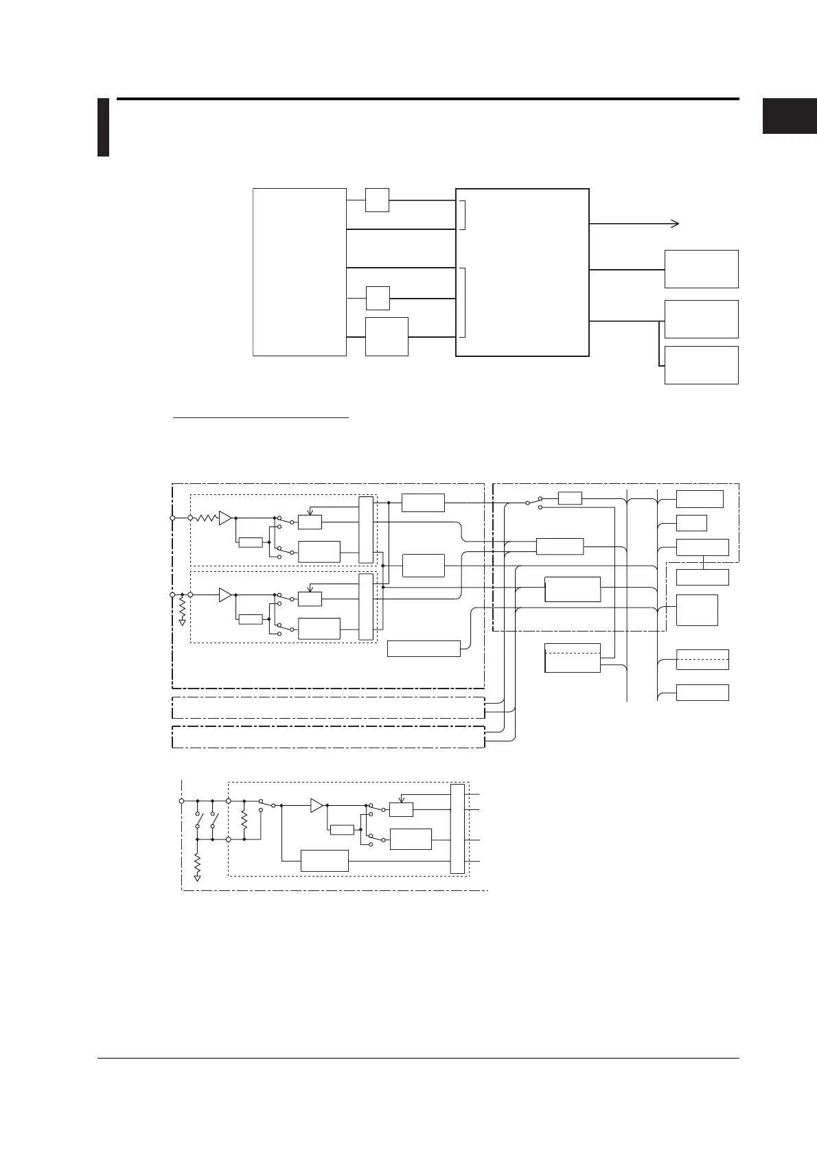
1.1 System Configuration and Block Diagram
System Configuration
Equipment
under
test
Voltage
input
Current
input
PT
CT
Ext.
sensor
Digital
power meter
WT210
(760401)
WT230
(760502,760503)
Analog output
GP-IB or
RS-232-C
Recorder
Personal
Computer
Ext. printer
or plotter
Contact / relay output
Input
either
one
Input
either
one
Block Diagram
Input section ( input element 1)
Input section ( input element 2)
Input section ( input element 3)
CPU section
Voltage input section
LPF
A/D
Zero Cross
Detector
ISO
A/D
interface
Lead/Lag
Detector
EEPROM
CPU
PLL
RAM
EEPROM
D/A Output
Serial
(RS-232-C)
GP-IB
ROM
RAM
or
DSP
(For WT210,
option)
(Option)
(Option)
(Option)
Current input section
LPF
A/D
Zero Cross
Detector
ISO
Current input section
LPF
A/D
Zero Cross
Detector
Current Over
Detector
ISO
WT210’s Current input section
Sampling
Clock
Frequency
Detector
Harmonics
Key & Display
Controller
Comparator
7-segment
LED
Model Input Section
760401 Built-in input element 1
760502
760503
Built-in input element 1 and 3
Built-in input element 1, 2, and 3

 Loading...


