S-15
IM 760401-01E
Startup Guide
6.
Press
ELEMEN
of display C to select input element 2.
Each time
ELEMEN
is pressed the element indicator character of display C illuminates in the
order shown below. The wiring system of the circuit on the primary side of the inverter
is single-phase, two-wire, and the circuit is connected to input element 2 of the WT230.
To show the measured value of input element 2 on display C, we illuminate input
element 2.
Display C
ELEMENT ELEMENT ELEMENT ELEMENT
2
1
2
3
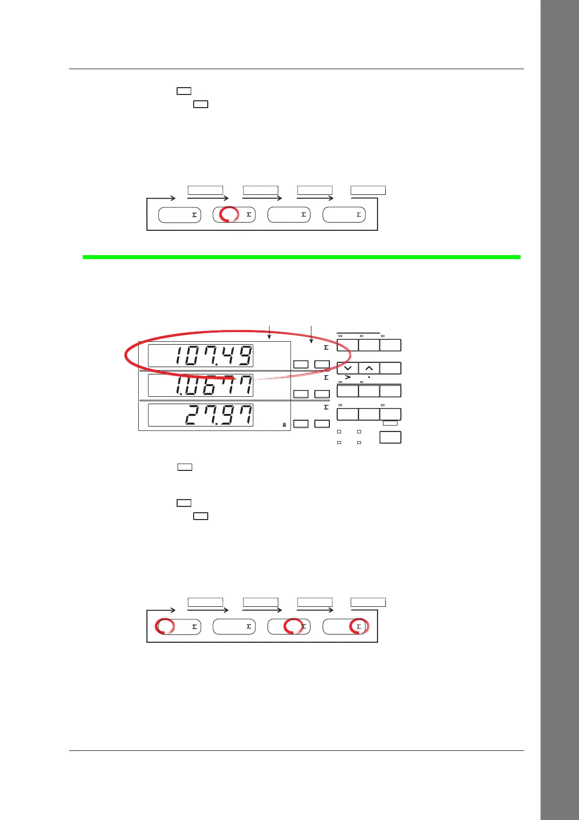
Displaying the Voltage of the Secondary Side of the Inverter on Display A
Carry out the following procedure to display the voltage of the secondary side of the inverter
on display A.
A
B
C
VOLTAGE
AUTO
MODE
CURRENT
AUTO
RANGE
MAX HOLD
TRIG
CAL
INTEGRATOR
INTEG SET
SHIFT
KEY LOCK
1P3W
3P3W
3P4W
3V3A
OUTPUT
HARMONICS
MEMORY
REMOTE
FUNCTION
ELEMENT
HOLD
ENTER
RESET
WIRING
START STOP
LOCAL
SETUP
1
V
A
W
23
FUNCTION
ELEMENT
123
FUNCTION
ELEMENT
123
Function indicator Element indicator
7.
Press
FUNCTIO
of display A to select function V.
For details, see step 1 of page S-10.
8.
Press
ELEMEN
of display A to select input element 1, 3 or Σ.
Each time
ELEMEN
is pressed the element indicator character of display A illuminates in the
order shown below. The wiring system of the circuit on the secondary side of the
inverter is three-phase, three-wire, and the circuit is connected to input elements 1 and
3 of the WT230. To show the measured value of input element 1, 3, or Σ on display A,
we illuminate input element 1, 3, or Σ.
Display A
ELEMENT ELEMENT ELEMENT ELEMENT
1
3 Σ
1
2
3
• When input element 1 is illuminated, the line voltage across phases U and V (see
page S-5) on the secondary side of the inverter is indicated.
• When input element 3 is illuminated, the line voltage across phases W and V (see
page S-5) on the secondary side of the inverter is indicated.
• When input element Σ is illuminated, the average of the line voltage across phases U
and V and the voltage across phases W and V on the secondary side of the inverter is
indicated. However, this value does not have any physical meaning.
Displaying Voltage, Current, and Active Power

 Loading...


