S-12 IM 760401-01E
Displaying Voltage, Current, and Active Power
<<For details, see section 5.1.>>
After selecting the measurement range (voltage and current ranges), select the measured
items to be displayed in each display.
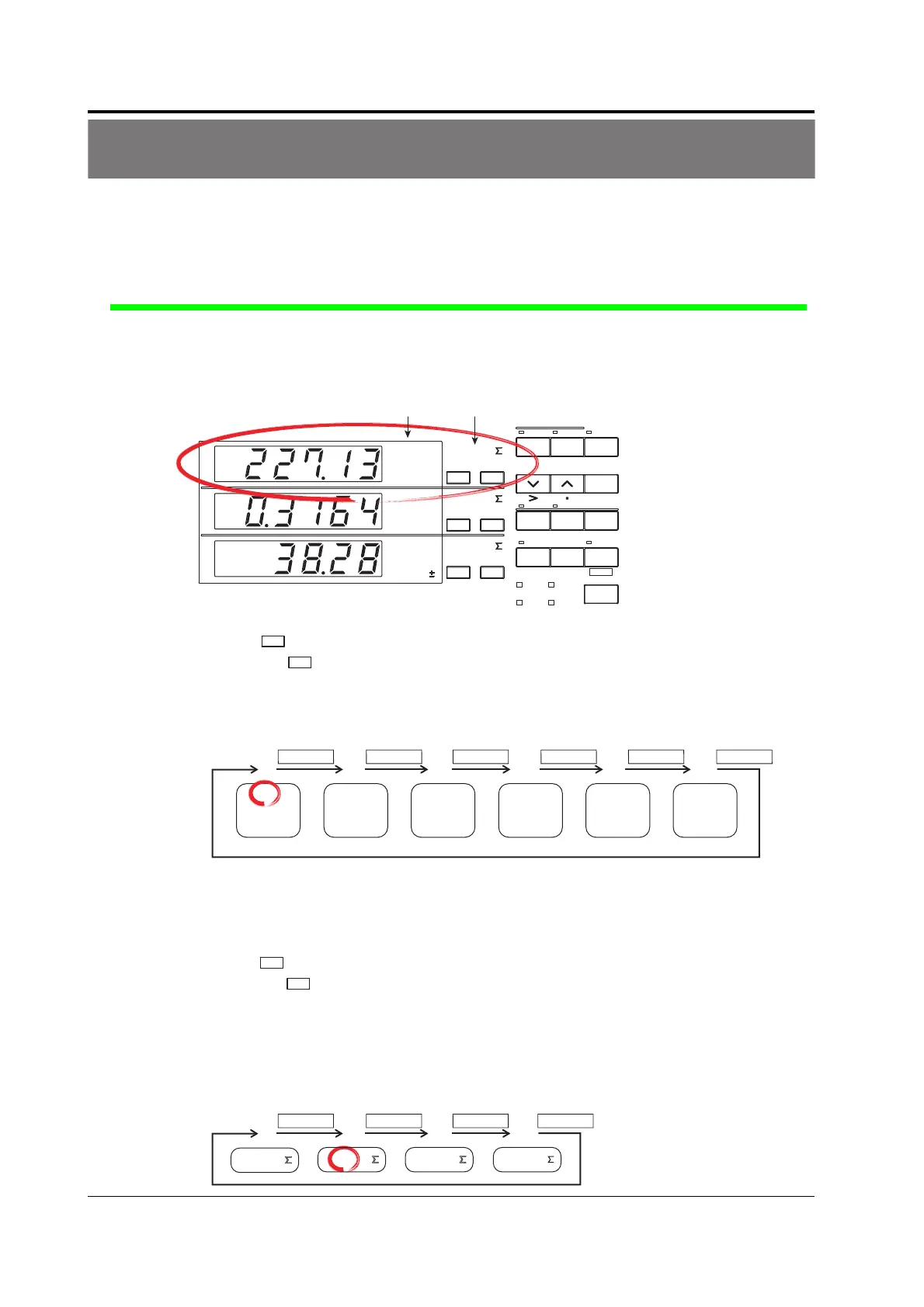
Displaying the Voltage on the Primary Side of the Inverter on Display A
Carry out the following procedure to display the voltage of the primary side of the inverter on
display A.
A
B
C
VOLTAGE
AUTO
MODE
CURRENT
AUTO
RANGE
MAX HOLD
TRIG
CAL
INTEGRATOR
INTEG SET
SHIFT
KEY LOCK
1P3W
3P3W
3P4W
3V3A
OUTPUT
HARMONICS
MEMORY
REMOTE
FUNCTION
ELEMENT
HOLD
ENTER
RESET
WIRING
START STOP
LOCAL
SETUP
1
V
A
W
23
FUNCTION
ELEMENT
123
FUNCTION
ELEMENT
123
Function indicator Element indicator
1.
Press
FUNCTIO
of display A to select function V.
Each time
FUNCTIO
is pressed the function indicator character of display A illuminates in the
order shown below. To show the measured voltage on display A, we illuminate function
V.
Display A
FUNCTION
V
FUNCTION FUNCTION FUNCTION FUNCTION FUNCTION
V
var
A
W
VA
TIME
The decimal point position moves so that the measured value can be displayed within
the number of digits available on display A. The appropriate prefix symbol (m(10
–3
),
k(10
3
), or M(10
6
)) of the unit illuminates accordingly.
2.
Press
ELEMEN
of display A to select input element 2.
Each time
ELEMEN
is pressed the element indicator character of display A illuminates in the
order shown below. The wiring system of the circuit on the primary side of the inverter
is single-phase, two-wire, and the circuit is connected to input element 2 of the WT230.
To show the measured value of input element 2 on display A, we illuminate input
element 2.
Display A
ELEMENT ELEMENT ELEMENT ELEMENT
2
1
2
3

 Loading...


