3-19
IM 760401-01E
Before Starting Measurements
3
3.10 Selecting the Wiring System (Applies Only to
the WT230)
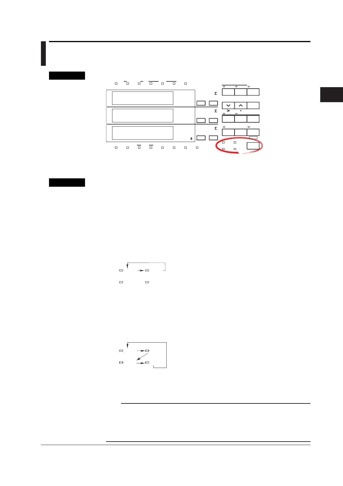
Keys
CHECK RANGE
MODE
UPDATE
SCALING
AVG
LINE FREQ
STORE RECALL
HARMONICS
KEY LOCK
FILTER
A
B
C
VOLTAGE VOLTAGE
VOLTAGE
AUTO
MODE
CURRENT
AUTO
RANGE
MAX HOLD
TRIG
CAL
INTEGRATOR
INTEG SET
SHIFT
KEY LOCK
1P 3W
3P 3W
3P 4W
3V 3A
OUTPUT
HARMONICS
MEMORY
REMOTE
MEAN
CURRENT RMS
DC
FUNCTION
ELEMENT
MAX HOLD
HOLD
ENTER
RESET
WIRING
START STOP
LOCAL
SETUP
1
m
V
k
A
V
TIME
ar
deg
h
h
VA
MW
m
VPF
k
A
MW
m
VHz
k
A
MW
23
FUNCTION
ELEMENT
123
FUNCTION
ELEMENT
123
%
The explanation given in this section uses WT230 as an example. For the
differences between the WT210 and the WT230, see section 2.2, “Operation
Keys and Functions/Element Display.”
Explanation
Wiring System
Press the WIRING key to select the wiring system. The selectable wiring systems
vary depending on the model.
• WT210 (model: 760401)
There is no wiring system selection function. A single input element (Element 1) is
installed. Measurement is possible only for the single-phase, two-wire system.
• WT230 (model: 760502)
The wiring system switches in the following order each time the WIRING key is
pressed. Two input elements (Element 1 and Element 3) are installed.
1P3W
3P3W
3P4W
3V3A
1P3W : Single-phase, two-wire system
3P3W : Three-phase, three-wire system
*In case of a measurement circuit of single-phase, two-wire system, and having selected
either element 1 or 3, selecting any of the above mentioned wring methods will result in
correct measurement/computation. However, the measurement/computation results in
case element Σ has been selected lose the physical meaning.
• WT230 (model: 760503)
The wiring system switches in the following order each time the WIRING key is
pressed. Three input elements (Element 1, Element 2, and Element 3) are
installed.
1P3W : Single-phase, two-wire system
3P3W : Three-phase, three-wire system
3P4W : Three-phase, four-wire system
3V3A : Three voltage, three current system
1P3W
3P3W
3P4W
3V3A
*In case of a measurement circuit of single-phase, two-wire system, and having selected
either element 1 or 3, selecting any of the above mentioned wring methods will result in
correct measurement/computation. However, the measurement/computation results in
case element Σ has been selected lose the physical meaning.
Note
Select the wiring system to match the circuit under measurement that is actually connected.
The internal processing of the WT230 varies depending on the selected wiring system. If the
selected wiring system does not match the actual circuit, measurements and computation will
not be correct. For the relationship between the wiring systems and the method of
determining the measured values or computed values, see page 16-6.

 Loading...


