S-14 IM 760401-01E
Displaying the Active Power on the Primary Side of the Inverter on Display C
Carry out the following procedure to display the active power of the primary side of the
inverter on display C.
A
B
C
VOLTAGE
AUTO
MODE
CURRENT
AUTO
RANGE
MAX HOLD
TRIG
CAL
INTEGRATOR
INTEG SET
SHIFT
KEY LOCK
1P3W
3P3W
3P4W
3V3A
OUTPUT
HARMONICS
MEMORY
REMOTE
FUNCTION
ELEMENT
HOLD
ENTER
RESET
WIRING
START STOP
LOCAL
SETUP
1
V
A
W
23
FUNCTION
ELEMENT
123
FUNCTION
ELEMENT
123
Function indicator Element indicator
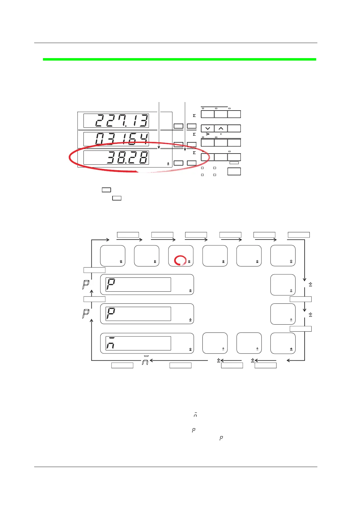
5.
Press
FUNCTIO
of display C to select function W.
Each time
FUNCTIO
is pressed the function indicator character of display C illuminates in the
order shown below. To show the measured active power on display C, we illuminate
function W.
Display C
FUNCTION
W
FUNCTION FUNCTION FUNCTION FUNCTION FUNCTION
FUNCTIONFUNCTIONFUNCTIONFUNCTION
h
W
h
W
h
W
Hz
A
h
A
h
A
h
A
VHz
W
A
V
C
C
V
C
A
FUNCTION
FUNCTION
FUNCTION
FUNCTION
&
&
• The decimal point position moves so that the measured value can be displayed within
the number of digits available on display C. The appropriate prefix symbol (m(10
–3
),
k(10
3
), or M(10
6
)) of the unit illuminates accordingly.
• Indicators “W h±” and “A h±” illuminate twice consecutively. For a description of these
items, see page 6-3.
• If the first digit of display C shows “
” (M), the result of computations such as the
efficiency, crest factor, and four arithmetic operations is displayed.
• If the first digit of display C shows
and function V is illuminated, the peak voltage is
displayed. If the first digit of display C shows and function A is illuminated, the peak
current is displayed.
Displaying Voltage, Current, and Active Power

 Loading...


