SECTION 9 - MAINTENANCE
JOHNSON CONTROLS
165
Form 201.47-ICOM1
Issue date: 17/11/2022
9
11.
test gas as applicable, make the necessary repairs,
repeat the leak tests, evacuate the chiller, and per-
form the time-based pressure hold test.
System evacuation
Ensure that power is removed from the
input side of the variable speed drive at all
times when the chiller is under vacuum
(less than atmospheric pressure). The
variable speed drive maintains voltage to
ground on the motor when the chiller is
o while voltage is available to the vari-
able speed drive. Insulating the properties
in the motor are reduced in vacuum and
may not insulate this voltage suciently.
Vacuum dehydration
Before you perform the final evacuation and system
charging, it is necessary to obtain a sufficiently dry
system. The following instructions have been assem-
bled to provide an effective method for evacuating and
dehydrating a system in the field. Although there are
several methods of dehydrating a system, the following
method produces one of the best results and provides
accurate readings of the extent of dehydration. The
equipment required to follow this method of dehydra-
tion consists of the following items:
• High resolution vacuum gauge (microns below
500)
• Chart that shows the relationship between dew
point temperature and pressure in microns (vacu-
um), see Table 20 on page 166.
• Vacuum pump that can pump a suitable vacuum
on the system
Follow the dehydration steps as closely as possible to
prevent moisture from becoming trapped in the sys-
tem. If you apply too deep of a vacuum, any trapped
moisture might freeze and not be exhausted as vapor.
Failure to remove all of the moisture can create acids
in the refrigerant circuit. These acids can damage inter-
nal system components over time and cause premature
failure of items such as the compressor, motor, and any
other devices sensitive to acid contact.
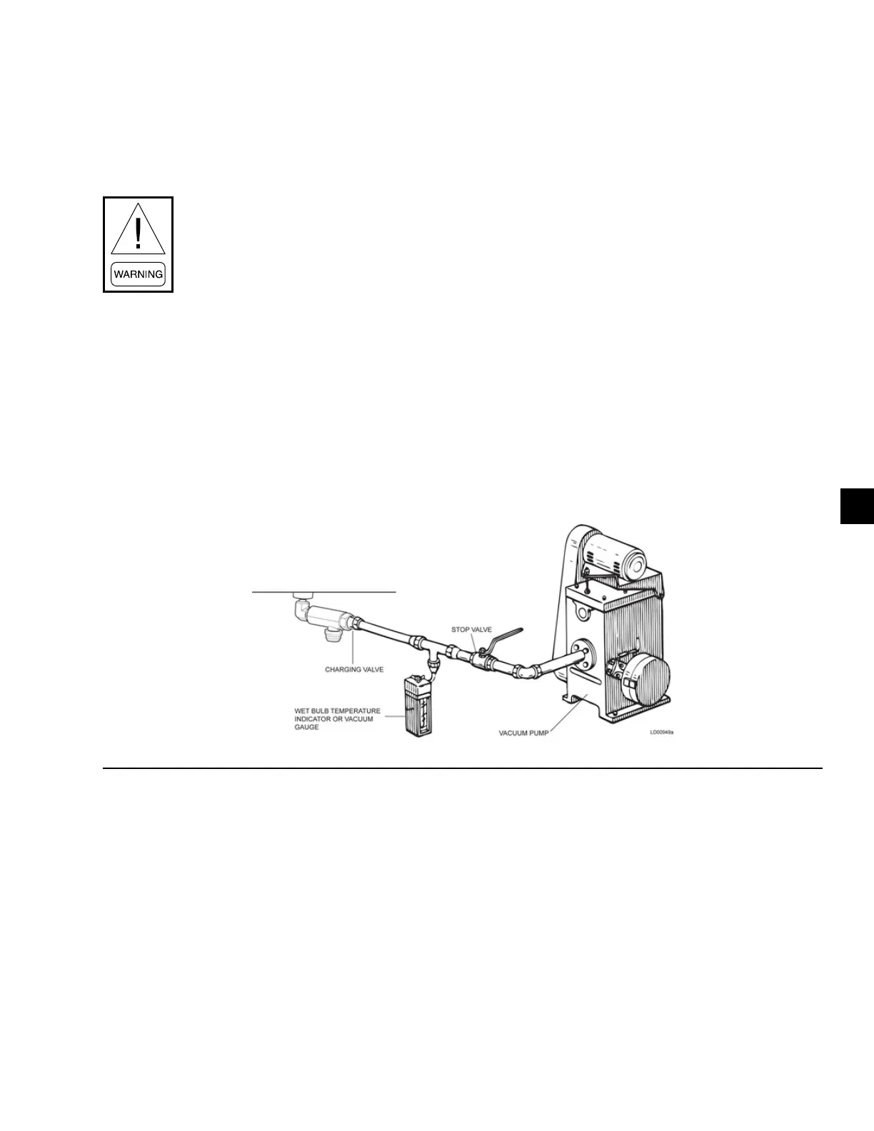
Figure 65 - Evacuation of the chiller operation

 Loading...


