SECTION 4 - INSTALLATION
JOHNSON CONTROLS
41
Form 201.47-ICOM1
Issue date: 17/11/2022
4
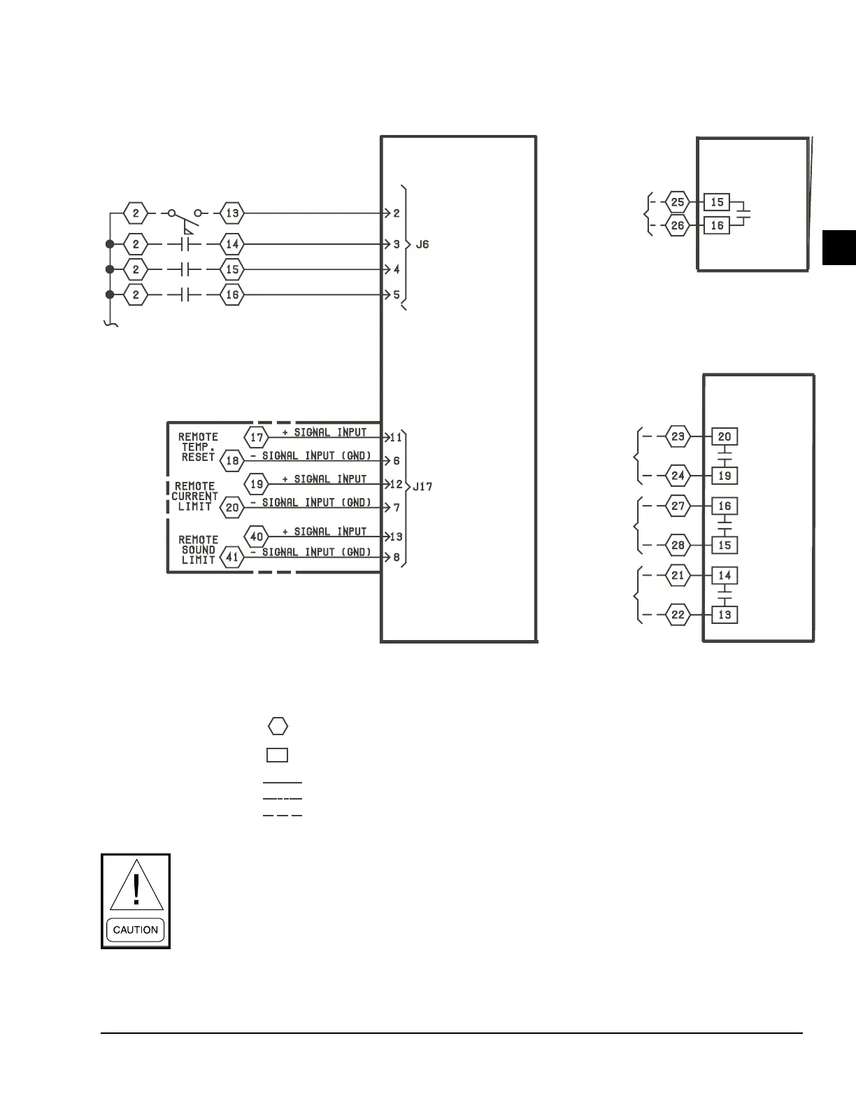
Figure 19 - Customer control connections
SYS. No. 1
ALARM
CONTACTS
SYS. No. 2
ALARM
CONTACTS
CHILLER
RUN
EVAP. PUMP
START
SIGNAL
SYS. No. 1 RUN PERM
SYS. No. 2 RUN PERM
FLOW SWITCH (-SF)
PRINT (PNT)
LEGEND
TERMINAL BLOCK FOR CUSTOMER CONNECTIONS
TERMINAL BLOCK FOR YORK CONNECTIONS
WIRING AND COMPONENTS BY YORK
OPTIONAL EQUIPMENT
WIRING AND/OR COMPONENTS BY OTHERS
RELAY
BOARD
No. 2
RELAY
BOARD
No. 1
CONTROL
BOARD
Customer control wiring
In subfreezing regions, failure to connect EVAP. PUMP START SIGNAL from terminal 23 and ter-
minal 24 to chilled water pump starter will void warranty, except when the water in the evaporator is
fully dried or appropriate concentration of glycol is reached in the water system.

 Loading...


