SECTION 5 - TECHNICAL DATA
JOHNSON CONTROLS
93
Form 201.47-ICOM1
Issue date: 17/11/2022
5
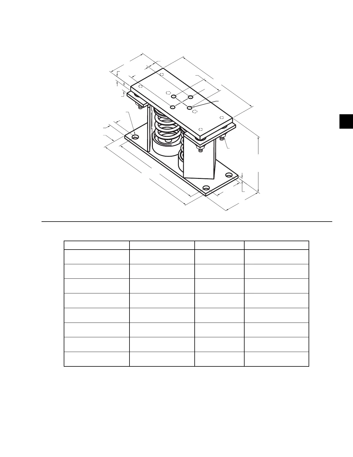
Two inch deflection, restrained spring isolator specifications
12"
5"
2-3/4"
12-1/4"
8-3/8"
OPER.
HEIGHT
14"
5/8"
3/8"
Ø3/4"
TYP.(4)
3-1/2"
5/8-11UNC
TYP. (4)
2-3/4"
3/4"
7/8"
1-1/8"
3/8" GAP
5"
1/2" LIMIT
STOP &
NUT
Notes:
1. All dimensions are in inches, interpret as per ANSI Y14.
2. Equipment must be bolted or welded to the top plate to meet allowable seismic ratings.
3. All springs are designed for 50% overload capacity with exception of the 029-25336-013 and 029-25336-014.
4. Consult JCI for concrete installation.
* Weight range (lb) * Weight range (kg) Model P/N Color
Up to 391 Up to 177 029-25336-006
(688690)
Green
392–604 178–274 029-25336-008
(688691)
Dark brown
605–740 275–336 029-25336-009
(688692)
Red
741–1020 337–463 029-25336-010
(688693)
Red/Black
1021–1437 464–652 029-25336-011
(688694)
Pink
1438–2244 653–1018 029-25336-012
(688695)
Pink/Gray
2245–2618 1019–1188 029-25336-013
(688697)
Pink/Gray/Orange
2619–3740 1189–1696 029-25336-014
(688698)
Pink/Gray/Dark brown
* Value is de-rated by 15%
Figure 43 - Two inch deflection isolator specifications
Table 15 - Two inch deflection isolator weights

 Loading...


