JOHNSON CONTROLS
30
SECTION 4 - INSTALLATION
Form 201.47-ICOM1
Issue date: 17/11/2022
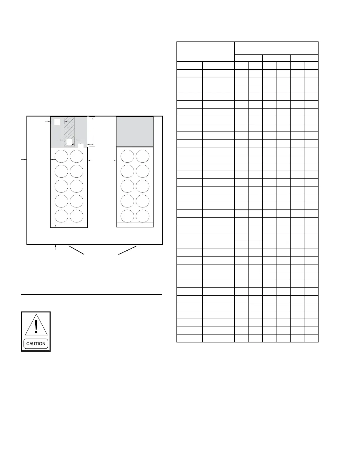
Recommended minimum clearances
The recommended clearances for the YVAA units are
as follows:
• Side to wall: 6 ft (1.8 m)
• Rear to wall: 6 ft (1.8 m)
• Control panel end to wall: 6 ft (1.8 m)
• Top: no obstructions whatsoever
• Distance between adjacent units: 10 ft (3 m)
Figure 9 - Acceptable minimum clearances around
and between units
1.8 m (6
ft)
Minimum
1.9 m (4.6 ft)
Minimum
3 m (10
ft)
Minimum
Control panel
C
A
A
Tube Removal
Clearance Area
Tube Removal
Clearance Area
B
Clearance dimensions provided in
Figure 9 on page 30 and Table 2 on
page 30 are necessary to maintain good
airow and ensure correct unit opera-
tion. It is also necessary to consider ac-
cess requirements for safe operation and
maintenance of the unit and power and
control panels. Local health and safety
regulations, or practical considerations
for service replacement of large compo-
nents, may require larger clearances than
those recommended.
Table 2 - Minimum evaporator tube removal clearance
Model YVAA
Tube removal
clearance dimensions
A B C
English Metric in. mm in. mm in. mm
0161 0571 29 737 30 762 60 1524
0201 0701 29 737 30 762 60 1524
0166 0586 29 737 30 762 60 1524
0211 0741 29 737 30 762 60 1524
0191 0671 29 737 30 762 60 1524
0169 0599 29 737 30 762 60 1524
0176 0616 29 737 30 762 72 1829
0214 0754 29 737 30 762 60 1524
0224 0782 29 737 30 762 72 1829
0254 0894 29 737 30 762 72 1829
0261 0921 29 737 30 762 72 1829
0196 0686 29 737 30 762 60 1524
0199 0699 29 737 30 762 72 1829
0234 0824 29 737 30 762 72 1829
0216 0756 29 737 30 762 60 1524
0226 0796 29 737 30 762 72 1829
0259 0919 29 737 30 762 72 1829
0266 0936 29 737 30 762 72 1829
0219 0769 29 737 30 762 60 1524
0229 0809 29 737 30 762 72 1829
0264 0924 29 737 30 762 72 1829
0269 0949 29 737 30 762 72 1829
0246 0866 29 737 30 762 72 1829
0294 1034 29 737 30 762 72 1829
0331 1161 29 737 30 762 72 1829
0306 1076 29 737 30 762 72 1829
0309 1089 29 737 30 762 72 1829
0334 1174 29 737 30 762 72 1829
0459 1549 29 737 30 762 72 1829
0491 1731 29 737 30 762 72 1829
0361 1271 29 737 30 762 72 1829
0391 1381 29 737 30 762 72 1829
0456 1606 29 737 30 762 72 1829
0399 1409 29 737 30 762 72 1829
0469 1649 29 737 30 762 72 1829

 Loading...


