SECTION 5 - TECHNICAL DATA
JOHNSON CONTROLS
91
Form 201.47-ICOM1
Issue date: 17/11/2022
5
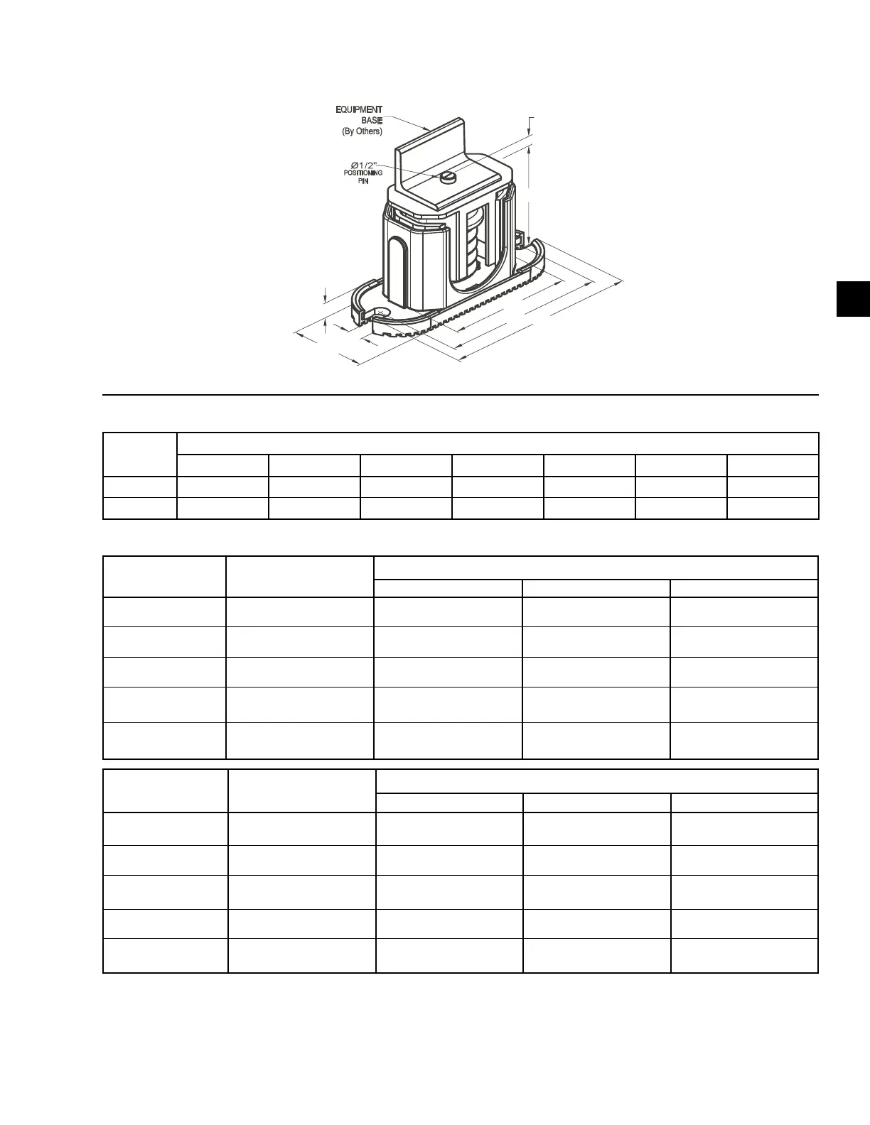
One inch deflection spring isolator specifications
Notes:
1. Use either all CP's or all CP2's at all locations on a unit.
2. Installation requires bolting or anchoring mount to support structure with a 2 x 0.625 in. diameter bolts or 2 x 0.5 in. diameter concrete
anchors.
3. All springs are designed for 50% over-travel.
Type A model P/N Color code
Rated capacity (for units with all load points less than 1785 lb [810 kg])
(lb) (kg) Part number
029-25334-002
(433668)
Black Up to 434 Up to 197 029-25334-002
029-25334-003
(433669)
Dark green 435–765 198–347 029-25334-003
029-25334-004
(433670)
Gray 766–1020 348–463 029-25334-004
029-25334-005
(433871)
White 1021–1156 464–524 029-25334-005
029-25334-006
(433872)
Gray/Red 1157–1785 525–810 029-25334-006
Type B model P/N Color code
Rated capacity (for units with any load point above 1518 lb [689 kg])
(lb) (kg) Part number
029-25334-008
(433997)
Dark purple Up to 1148 Up to 521 029-25334-008
029-25334-009
(433998)
Dark green 1149–1530 522–694 029-25334-009
029-25334-010
(433999)
Gray 1531–2040 695–925 029-25334-010
029-25334-012
(434000)
White 2041–2312 926–1049 029-25334-012
029-25334-013
(434001)
Gray/Red 2313–3570
1050–1619
029-25334-013
Mount
type
Dimension data (in.)
W D L B C T H
Type A 3 5/8 7 3/4 6 1/2 4-3/4 1/2 5 5/8
Type B 3 5/8 10 1/2 9 1/4 7 3/4 9/16 6
Figure 41 - One inch deflection isolator specifications
Table 13 - One inch deflection isolator dimensions
Table 14 - One inch deflection isolator weights

 Loading...


