SECTION 4 - INSTALLATION
JOHNSON CONTROLS
39
Form 201.47-ICOM1
Issue date: 17/11/2022
4
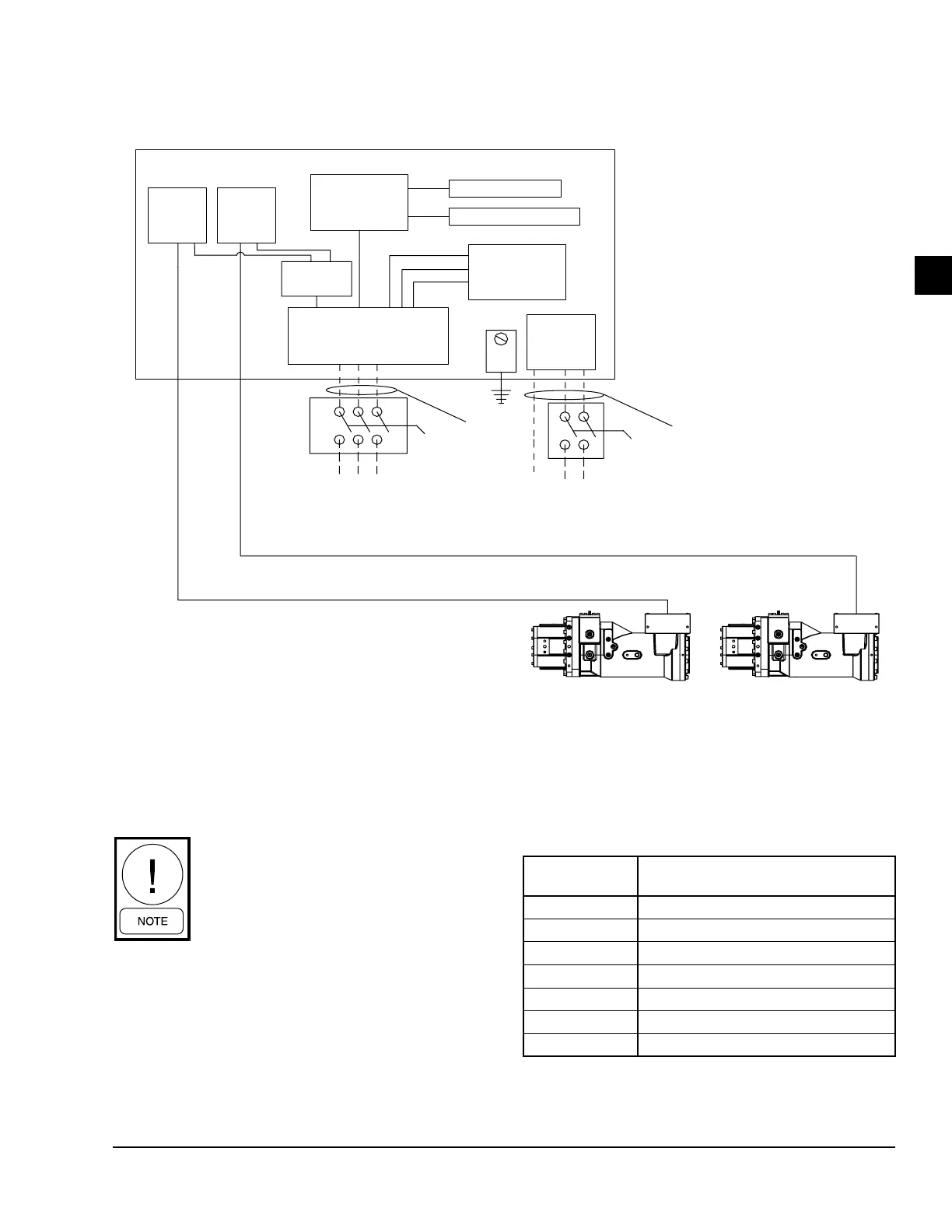
Figure 17 - Single point power wiring
Minimum Circuit Ampacity (MCA),
Minimum/Maximum Fuse Size, and
Minimum/Maximum Circuit Breaker size
vary on chillers based upon model and
options ordered. Consult YorkWorks or
the chiller data plate for electrical data
on a specic chiller.
Voltage utilization range
Rated voltage Utilization range
200/60/3 180–220
230/60/3 208–254
380/60/3 342–418
400/60/3 360–440
460/60/3 414–508
575/60/3 520–635
400/50/3 360–440
Power supply wiring
Single point wiring
LD18588a
UNIT MOUNTED ELECTRONICS
INVERTER
1
INVERTER
2
LINE
REACTOR
UNIT CONTROLS
EVAPORATOR HEATER
FAN
CONTACTORS
TERMINAL BLOCK
(CIRCUIT BREAKER - OPT)
(NON-FUSED DISCONNECT
SWITCH - OPT)
STANDARD
CONTROL
TRANSFORMER
FIELD PROVIDED
UNIT POWER
SUPPLY
GND
SEE NOTE 1
WATER BOX
HEATER
KIT
115V/60Hz
220V/50Hz
LN
PE/GND
SEE NOTE 1
COMPRESSOR SYSTEM 1 COMPRESSOR SYSTEM 2
Note 1: Dashed line represents customer wiring.

 Loading...


