JOHNSON CONTROLS
34
SECTION 4 - INSTALLATION
Form 201.47-ICOM1
Issue date: 17/11/2022
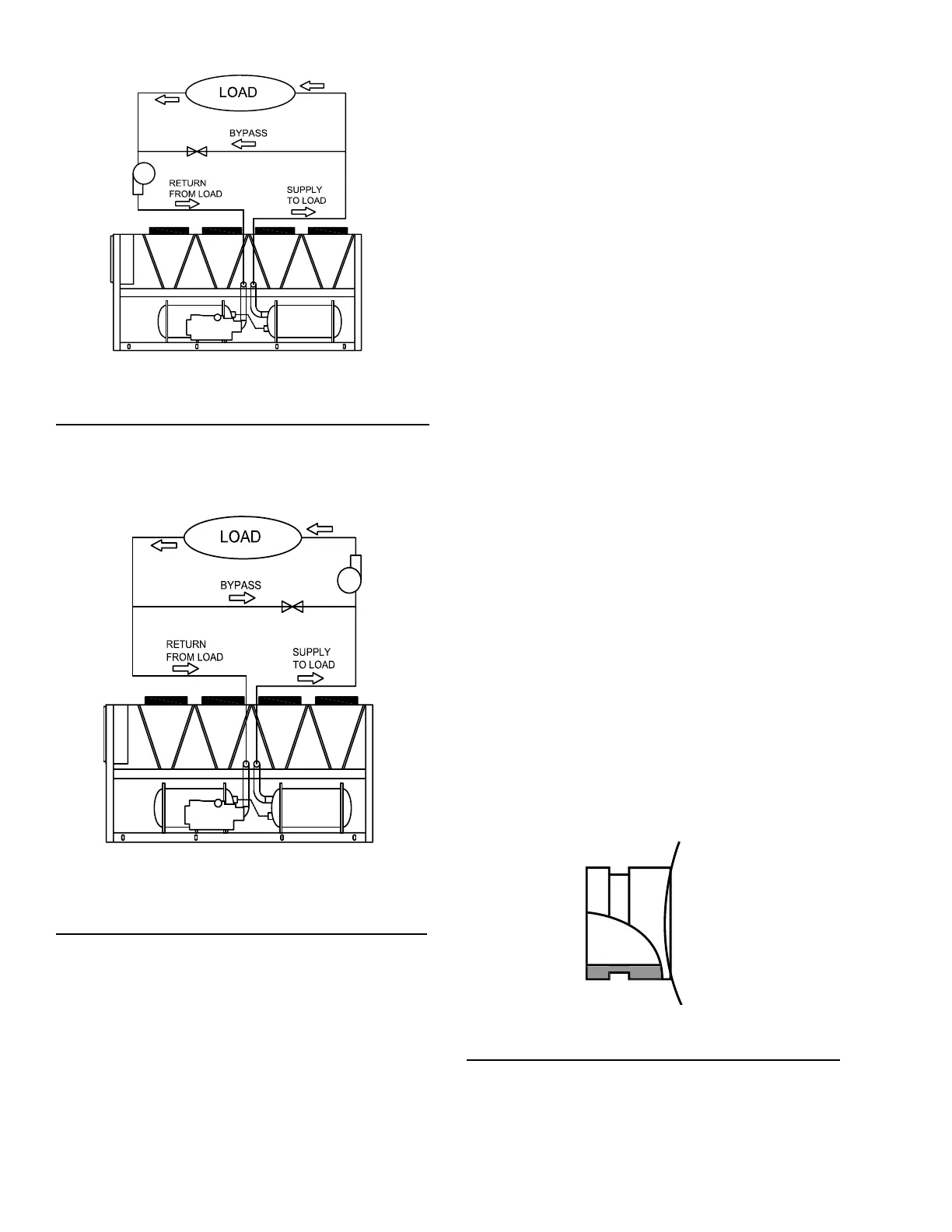
Figure 12 - Suggested layout for applications with
a flow rate less than the evaporator
minimum allowable flow rate
LD15049
In applications where the required flow rate is greater
than the evaporator’s maximum allowable, the chilled
water can be recirculated to the load.
Thermal storage
Thermal storage is the practice of storing cooling
energy during a period of little or no load and/or low
energy costs for use during periods of high load and/
or energy costs. Conventional cooling systems pro-
duce cooling when it is needed which is commonly
during times of peak demand. Thermal storage allows
generation of cooling capacity to occur during off-
LD15051
Figure 13 - Suggested layout for applications with
a flow rate greater than the evaporator
maximum allowable flow rate
peak periods and store that capacity to meet future
cooling requirements. Using thermal storage can result
in smaller equipment sizes, thereby reducing capital
cost, and also can result in significant energy cost sav-
ings.
The YVAA has special control logic to be able to pro-
duce chilled leaving brine temperatures below 4.4°C
(40°F) so as to supply a storage tank with chilled liquid
during times of low demand. YVAA chillers selected
for thermal storage operation can also be selected to ef-
ficiently provide chilled fluid at nominal cooling loads.
Variable primary flow
Johnson Controls recommends a maximum 10% per
minute flow rate of change, based on design flow, for
variable primary flow applications. Provide 8 gal to
10 gal per chiller ton (8.6 L to 10.8 L per cooling KW)
system water volume. Insufficient system volume and
rapid flow changes can cause control problems or can
even cause chiller shutdowns. There are many other
design issues to evaluate with variable primary flow
systems. Consult your Johnson Controls Sales Of-
fice for more information about successfully applying
YVAA chillers.
Connection types and sizes
For connection sizes relevant to individual models see
Section 5 - Technical data.
Evaporator connections
Standard chilled liquid connections on evaporators are
of the grooved type for ASME and PED marked units
and Flange type for GB marked units. See Figure 15 on
page 36 for flange dimensions on GB marked ves-
sels.
Figure 14 - Grooved nozzle
LD10494

 Loading...


