Operation principle and hardware description 29
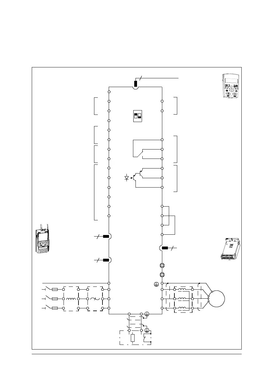
Overview of power and control connections
The diagram gives an overview of connections. I/O connections are parameterable.
See chapter Application macros on page 107 for I/O connections for the different
macros and chapter Electrical installation on page 49 for installation in general.
RONO
RONC
3
9
DI1
DI2
DI3
DI4
DI5
+24 V
Aux. voltage output
+24 V DC, max. 200 mA
DOSRC
GND
DCOM
DOOUT
DOGND
Digital/frequency output,
PNP transistor type
30 V DC, max. 100 mA
Relay output
250VAC / 30VDC/6A
V
mA
GND
+10V
Reference voltage
+10 V DC, max. 10 mA
AI2
Analog input 2
GND
AI1
Analog input 1
0…10 V
SCR
Screen
Analog output
0…20 mA
AI1
AI2
L1 U2
V2
W2
AC motor
M
3 ~
EMC
VAR
EMC filter grounding screw
Varistor grounding screw
ROCOM
PROGRAMMABLE RELAY
AND DIGITAL OUTPUTS
Control panel
(RJ-45)
Modbus RTU
(RS-232)
11
17
18
19
20
21
22
AO 7
GND 8
12
13
14
15
16
10
L2
L3
PE
6
5
1
2
PROGRAMMABLE
DIGITAL INPUTS
4
FlashDrop
U1
V1
W1
S1
8
6
6
DI5 can also be used
as a frequency input
t°
OUT1
OUT2
IN1
IN2
X1C:STO
Brake resistor
BRK+ BRK-
Fieldbus adapter
10
brake
chopper
1
2
3
4
Extension modules
MPOW-01
MREL-01
MTAC-01
Output
choke
Common DC
or
PE
ON
21
Input
choke
EMC
filter
3-phase
power
supply,
200…480
VAC

 Loading...


