222 Actual signals and parameters
20 LIMITS Drive operation limits.
Speed values are used in vector control and frequency
values are used in scalar control. The control mode is
selected by parameter 9904 MOTOR CTRL MODE.
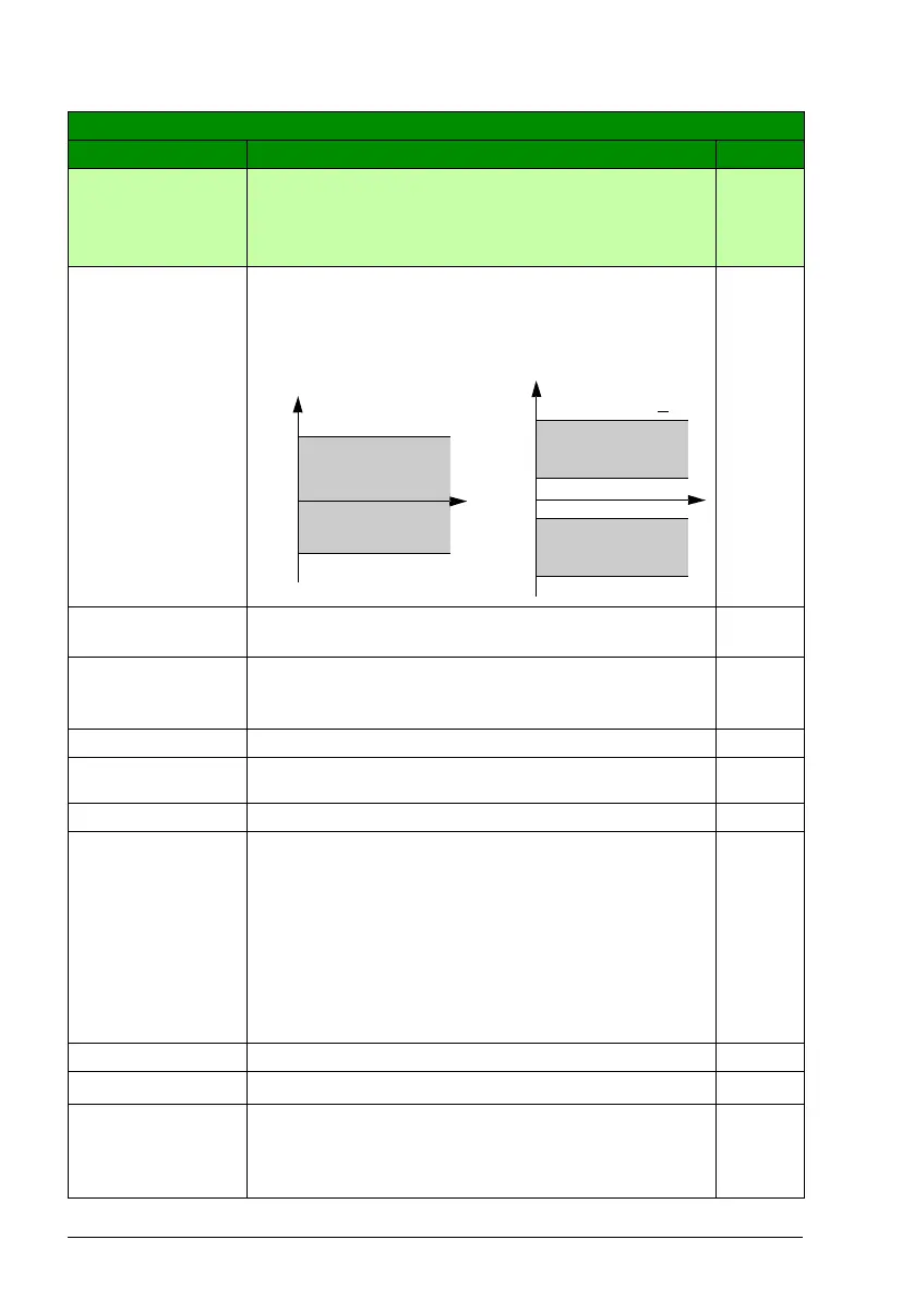
2001 MINIMUM
SPEED
Defines the allowed minimum speed.
A positive (or zero) minimum speed value defines two
ranges, one positive and one negative.
A negative minimum speed value defines one speed range.
0rpm
-30000…
30000 rpm
Minimum speed 1 = 1 rpm
2002 MAXIMUM
SPEED
Defines the allowed maximum speed. See parameter 2001
MINIMUM SPEED.
E: 1500 rpm
/
U: 1800 rpm
0…30000 rpm Maximum speed 1 = 1 rpm
2003 MAX
CURRENT
Defines the allowed maximum motor current. 1.8 · I
2N
A
0.0…1.8 · I
2N
A Current 1 = 0.1 A
2005 OVERVOLT
CTRL
Activates or deactivates the overvoltage control of the
intermediate DC link.
Fast braking of a high inertia load causes the voltage to rise
to the overvoltage control limit. To prevent the DC voltage
from exceeding the limit, the overvoltage controller
automatically decreases the braking torque.
Note: If a brake chopper and resistor are connected to the
drive, the controller must be off (selection DISABLE) to
allow chopper operation.
ENABLE
DISABLE Overvoltage control deactivated 0
ENABLE
Overvoltage control activated
1
EN WITH
BRCH
Both braking chopper and overvoltage controller are
enabled so that the braking chopper capability is used to its
maximum and the overvoltage controller is activated above
that.
2
All parameters
No. Name/Value Description Def/FbEq
2002
2001
0
Speed
2001 value is < 0
2001 value is > 0
2002
2001
0
-(2001)
-(2002)
t
t
Allowed
speed range
Allowed
speed range
Allowed
speed range
Speed

 Loading...


